This thread has been locked.

If you have a related question, please click the "Ask a related question" button in the top right corner. The newly created question will be automatically linked to this question.

UCC27282: Uncorrected behavior of simulation UCC27282 in Pspice for TI

Part Number: UCC27282
Other Parts Discussed in Thread: UCC27284, UCC27212

Dear E2E,

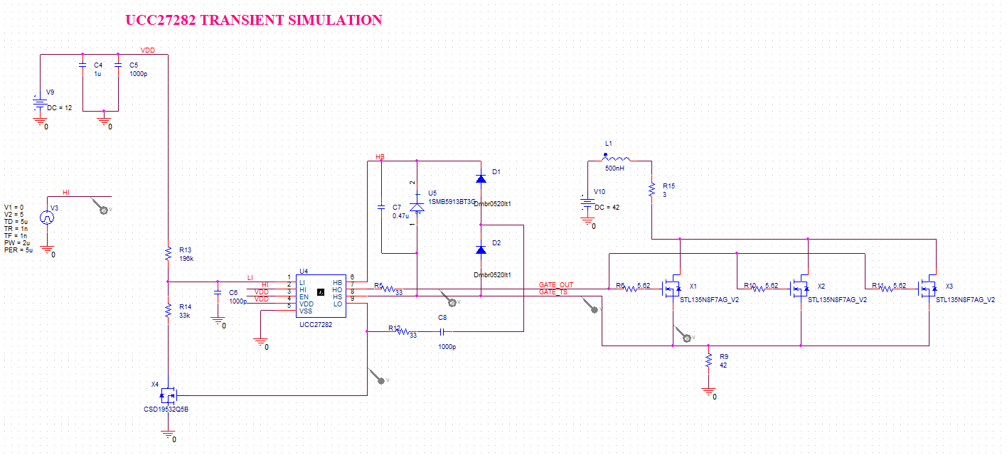
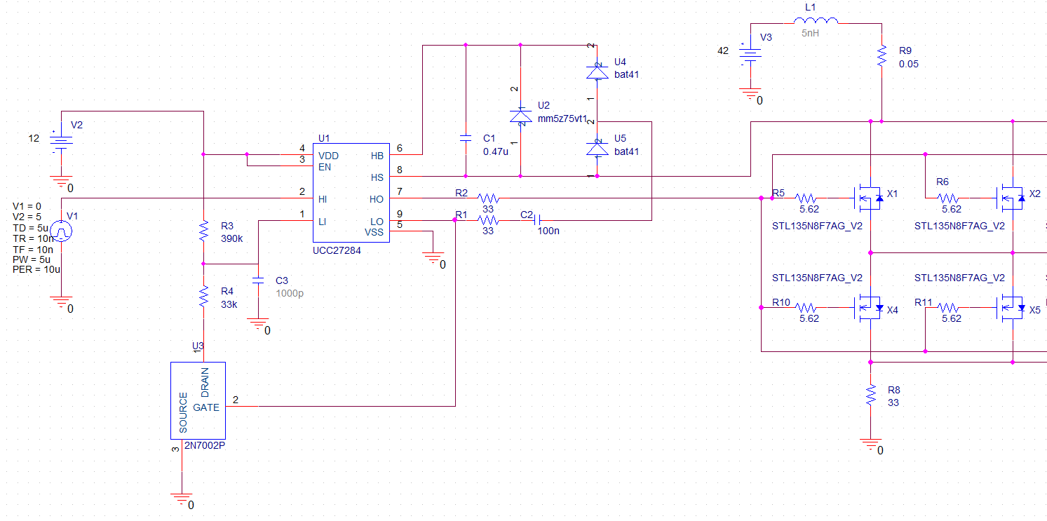
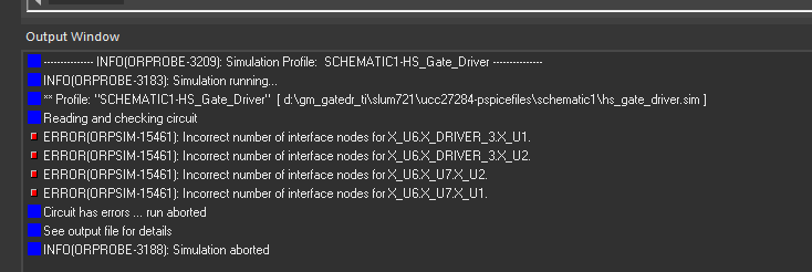
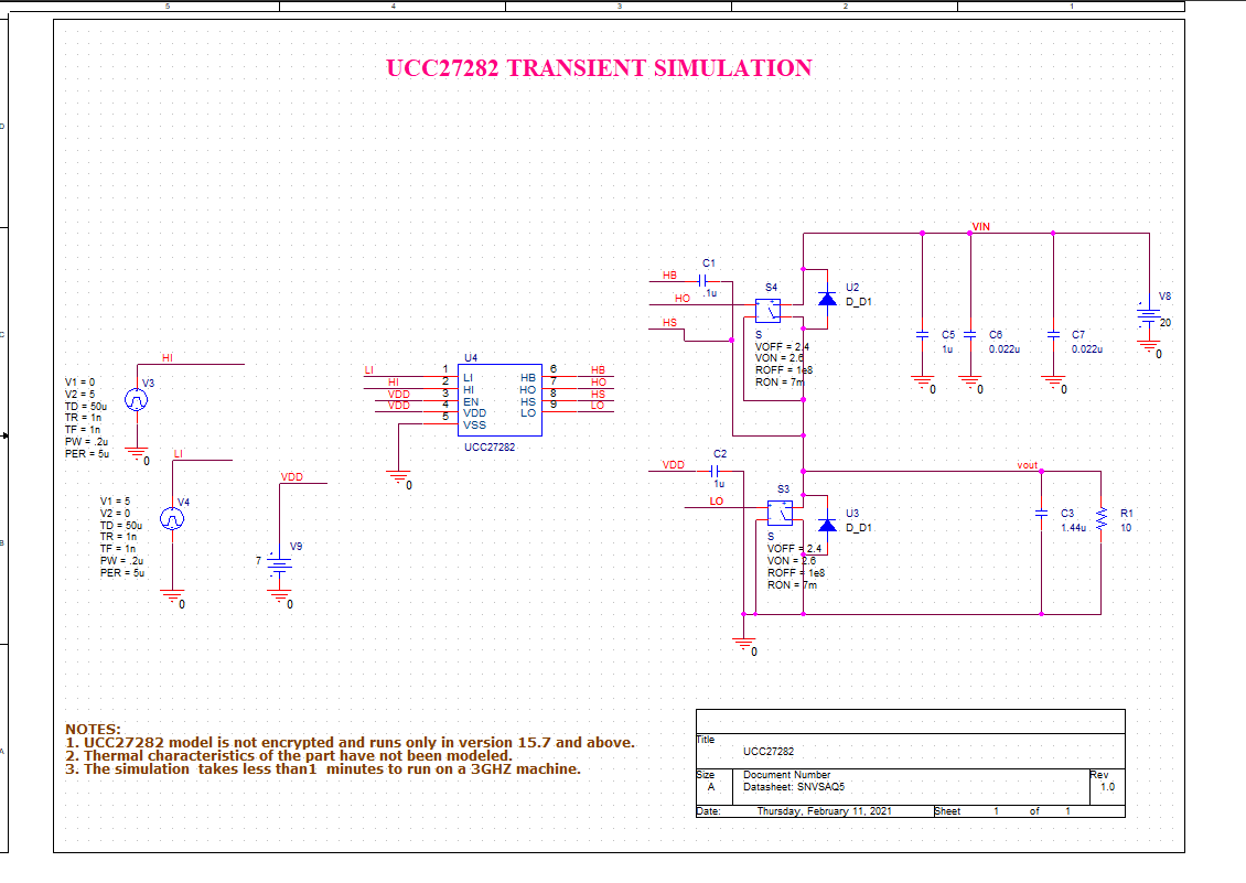
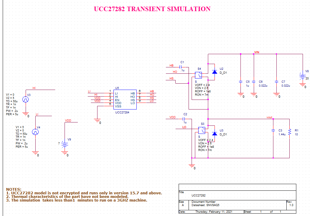
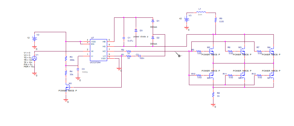
Could you please take a look at the simulation of UCC27282 with generated 3rd parts if there are any issues with it? When I compare the datasheet functions description and simulation I expect the gate output pulse  HO signal for MOSFETs similar to input pulses HI. But there is no correct HO signal. I did not have a lot of experience with PSpice for TI so I am not sure if the reason for the issue with the simulation tool or circuit.

Reference PSpice design.zip

Thanks for any comments,

Serhii.

  • Hello Serhii,

    Thanks for reaching out.

    Can you share details of the issue you're seeing? Is your simulation running and HO output showing the wrong the voltage? or are running into errors when attempting to import the models and run the simulation?

    Regards,

    -Mamadou

  • Hello Mamadou

    The signal on GATE_OUT(HO pin) should reflect on the HI signal as I understand. but I don't see the correct signal on the HO pin. Please see the attached plot in the attachment.

    Also schematic attached:

    0410.SCHEMATIC1 _ PAGE1.pdf

    Also after 45% of the simulation, it stops with errors:

    • ERROR(ORPSIM-15138): Convergence problem in Transient Analysis at Time = 13.69E-06.
    • These voltages failed to converge:
    • V(N16733537) = -5.520mV \ 60.31uV
    • V(N16727764) = 1.805uV \ 3.537uV
    • V(X_U4.U1_N16707366) = -1.575uV \ 156.95nV
    • V(X_U4.U1_LOH) = 1.887uV \ 3.537uV
    • V(X_X4.10) = 81.39mV \ 62.04mV
    • ERROR(ORPSIM-15661): 5 of 5 errors shown. See output file for complete list
    • These supply currents failed to converge:
    • I(X_U4.E_U1_E2) = 9.95nA \ 454.75fA
    • I(X_U4.E_U1_E1) = 4.337nA \ -14.55pA
    • I(X_U4.E_U1_E4) = -239.33pA \ -5.096pA
    • I(X_U4.E_U1_E3) = 0A \ 3.360pA
    • I(X_X1.E2) = -20.49nA \ 2.956pA
    • ERROR(ORPSIM-15661): 5 of 11 errors shown. See output file for complete list
    • ERROR(ORPSIM-15660): These devices failed to converge
    • X_U5.D1
    • X_X4.M1

    Regards,

    Serhii

  • Hello Serhii,

    Thanks for the details. 

    ON your waveform, I do not understand why HI voltage is up to 35V while your schematic shows that V3 on HI should only be from 0 to 5V, can you confirm?

    Additionally, can you also confirm that X1 and the other FETs as well as the UCC27282 .lib file are associated to the simulation project. In some cases, the unencrypted .lib files might not be associated to the "model libraries" section of the project file.

    As sanity, were you able to run the default project file on the UCC27282 product folder page before adding the parallel FETs?

    Regards,

    -Mamadou  

  • Hi Mamadou,

    The header of the waveform is below of plot in the attached image to the previous comment. The HI signal has two 5V pulses and it looks correct.

    I create parts by Tool->Generate part. As I understand it automatically associates with the .lib file. Also, I added the .lib library in Simulation settings.

    Yes, I can run the default project, and it works properly.

    Regards,

    Serhii

  • Hi Serhii,

    Thanks for the details.

    I have reviewed the schematic file and it is unclear why HS is connected to the drain of the n-ch FETs. This may be "confusing" the model as HO is supposed to be referenced to HS to enable the gate voltage on the floating FETs.  

    To turn the FETs on, the model of the FETs and the driver expect to see a higher voltage on HO with respect to source of the floating FETs (HS) while your current setup appears to tie HS of the driver to drain in which case, MOSFET may not turning-on creating the convergence issues that your seeing.

    I suggest tying HS to the source and of the FET to allow the FETs to turn-on when the charge pump is discharging.

    Regards,

    -Mamadou  

  • Hi Mamadou,

    I have connected the TS signal to the source of FET and it still stopping simulation at some stage. Please see Pictures of schematic, Waveforms, and output windows.

    Schematic:

    Waveform:

    Output window:

    Regards,

    Serhii

  • Hi Serhii,

    Our expert is reviewing the latest information and will get back to you promptly.

    Thanks for your patience.

    Best regards,

    Andy Robles

  • Hello Serhii,

    In looking at the schematic, this looks like a high side switch with the LO output being used for the HB bias charge pump. In this case, the LO and HO outputs need to be able to be on at the same time since LO will be switching when you want to turn on the HO output with a high on HI.

    For this operation the UCC27282 will have issues since this device has input interlock which will not allow LO and HO to be on at the same time. For this operation, use the UCC27284 which is the same as the UCC27282 regarding specifications but the UCC27284 does not have the input interlock and can operate with LO and HO on at the same time.

    Confirm if this addresses your questions or you can post additional questions on this thread.

    Regards,

  • Hello Serhii,

    My apologies for the delay.

    I have further reviewed your schematic and I failed to mention this last mention but the driver you're currently using is not suitable for this application given the internal cross conduction protection circuitry preventing HO and LO from being high simultaneously.

    I recommend trying the UCC27212 instead which has independent output LO and HO allowing to drive both channels simultaneously.

    Regards,

    -Mamadou

  • Hi Mamadou,

    Sorry for the late response. I have tried to run the reference simulation of UCC27212 with the reference design. And I could once, but after the restart of PSpice, I have got an error:

    --------------- INFO(ORPROBE-3209): Simulation Profile: UCC27212_Published-Published ---------------
    INFO(ORPROBE-3183): Simulation running...
    ** Profile: "UCC27212_Published-Published" [ E:\Downloads\slum588\ucc27212_trans-pspicefiles\ucc27212_published\published.sim ]
    Reading and checking circuit
    INFO(ORPSIM-15423): Unable to find index file ucc27212_trans.ind for library file ucc27212_trans.lib.
    INFO(ORPSIM-15422): Making new index file ucc27212_trans.ind for library file ucc27212_trans.lib.
    Making index file for library E:\Downloads\slum588\ucc27212_trans.lib
    Please be patient. This may take several minutes...
    ERROR(ORPSIM-15108): Subcircuit SI7368DP used by X_Q4 is undefined
    ERROR(ORPSIM-15108): Subcircuit SI7368DP used by X_Q3 is undefined
    ERROR(ORPSIM-15461): Incorrect number of interface nodes for X_U1.X_DRIVER_3.X_U1.
    ERROR(ORPSIM-15461): Incorrect number of interface nodes for X_U1.X_DRIVER_3.X_U2.
    ERROR(ORPSIM-15461): Incorrect number of interface nodes for X_U1.X_U7.X_U2.
    ERROR(ORPSIM-15461): Incorrect number of interface nodes for X_U1.X_U7.X_U1.
    Circuit has errors ... run aborted
    See output file for details
    INFO(ORPROBE-3188): Simulation aborted

    The goal of the previous version with UCC27282 uses the application notes: Implementing a Battery Disconnect Switch Using 100-V Half-Bridge Gate Drivers.

    On the real board will be used UCC27284QDQ1, but I didn't find this part in the library. Is there exist a model for UCC27284?

    Regards,

    Serhii

  • Hello Serhii,

    It is not clear why the simulation ran once with no issues and then showed errors finding the device index files.

    I see that there seemed to be an issue with the MOSFETs as well as shown below.

    ERROR(ORPSIM-15108): Subcircuit SI7368DP used by X_Q4 is undefined
    ERROR(ORPSIM-15108): Subcircuit SI7368DP used by X_Q3 is undefined

    I would try downloading the driver and MOSFET subcircuit files again.

    The spice model for the UCC27284 is in the product folder under the design tools and simulation. I see the model listed in the following link.

    https://www.ti.com/product/UCC27284#design-development

    Confirm if this addresses your questions or you can post additional questions on this thread.

    Regards,

  • Hello Richard,

    I have created another project for UCC27284, and got another notification. Please see the schematic and notification:

    How can I run this circuit?

    Regarding the previous issue, seems I accidentally reinstall the Model library.

    Regards,

    Serhii

  • Hello Serhii,

    I have forwarded your latest feedback to a co worker for additional review.

    You should try the option to modify the markers settings to see if you can change to accommodate the IC subcircuit.

    Also I see a previous comment, I assume on the UCC27212 that you accidentally reinstalled the libraries. Do you have the circuit with the UCC27212 working? If so that device can be used to review the circuit operation, the lab testing of the UCC27212 and UCC27284 in this circuit is similar.

    Confirm if this addresses your questions, or you can post additional questions on this thread.

    Regards,

  • Hello Richard,

    Many thanks for helping out. Unfortunately, I still get an issue with the UCC27212 reference circuit.
    I hoped that the updating library heps with it but it didn't.

    When I updated the design with UCC27212 instead of UCC27284 I got a similar output

    Regards,

    Serhii

  • Hello Serhii,

    I want to consult with a coworker to see if they have seen similar errors and the resolution.

    Let me get back within the next day or two.

    Regards,

  • Hello Serhii,

    I reviewed the thread messages with the information and error messages with a co worker.

    We concentrated on the simulations you have run with the UCC27212 and UCC27284 since the application circuit will not work properly with the UCC27282.

    It looks like in one case the error messages are on the power MOSFET devices, and the most recent post indicates a message on the 2N7002 signal FET.

    I would suggest starting back with a basic circuit including the driver and confirm the operation. A good starting place is to download the UCC27282 Pspice Transient Model from the UCC27282 design and development tools. This circuit has ideal diodes and switches included in a power circuit which can be used to build your specific application circuit.

    Once you confirm that the simulation is running, start by replacing the UCC27282 model with the UCC27212 driver model and confirm operation. Once that is confirmed, start adding the components for the application circuit. use ideal device models where possible for diodes and transistors initially to confirm operation.

    Then you can replace the ideal devices with specific models one by one to minimize the possibility of multiple device models having some issue or errors.

    Confirm if this addresses your questions, or you can post additional questions on this thread.

    Regards, 

  • Hello Richard,

    Thank you for the direction.

    I have followed the recommendations, but I still can not run the simulation with UCC27212 and UCC27284; See the screen of the simulation. It seems, that the issue with models or way to generate parts.

    Reference simulation of UCC27282:

    Plot of UCC27282:

    Updated with UCC27284. Schematic:

    Report:

    Updated with UCC27212. Schematic:

    Report:

    Regards,

    Serhii

  • Hello Serhii,

    Thank you for the latest status and simulation images. In the case of the simulation using the UCC27284, I would suggest trying this schematic again since the error message indicates a limitation on the number of markers on the internal device. Which seems a little more clear than the error message on the UCC27212.

    As an experiment, on the UCC27284 schematic, run the simulation again, and when you get the error message click OK on the error message and change the number of markers in the marker settings. You will have to see what the setting is when you select OK, but I suspect that there are more than 3 markers selected. Change the number of markers to from 1 to 3, you can try both, to see if this resolves this error message.

    Confirm if this addresses your questions or you can post additional questions on this thread.

    Regards,

  • Hi Richard,

    I have removed a couple of markers except one, and I could run the simulation for UCC27284. So I go ahead and update it to the circuit, that I need with ideal components, however, there appears a message:
    Schematic:

    Output:

    Regards,

    Serhii

  • Hello Serhii,

    Spice seems to have trouble with nets in the circuit that may have voltage ringing, high dV/dt or dI/dt.

    I see you have some inductance, L1 in the circuit which combined with the MOSFET model capacitance may result in voltage ringing. I would remove L1 for now and short the connection.

    You can try increasing the accuracy values in the table which means the engine can run with a solution with a wider margin of error.

    I would delay the HI input for a long period to allow the bias circuit to stabilize before changing state of the high side switch.

    Confirm if this addresses your questions, or you can post additional questions on this thread.

    Regards,

  • Hello Richard,

    I have updated a few spins with different values in the simulation but I still get a notification:
    Schematic:

    Output:

    Regards,

    Serhii

  • Hello Serhii,

    I looked at the schematic, and I think the HS pin of the driver needs to be connected to the source of the MOSFET's. Leave all other connections of the HS pin of the driver in place, and just disconnect from the drain and connect to the source of the MOSFET's. I think there is a conflict in the existing connection.

    Confirm if this addresses your questions, or you can post additional questions on this thread.

    Regards,

  • Hello Richard,

    After connecting the HS pin to the source I still see the same notification about PSpice simulation settings. Plus there is this notification:


    Regards,

    Serhii

  • Hello Serhii,

    For the circuit to work correctly, the HS of the driver needs to be connected to the MOSFET source, or equivalent.

    For the error message, I think previously you confirmed if you select OK and change the markers to 1 the sim runs OK.

    I think it makes sense to do a couple of things. The schematic below ran OK based on your feedback, with the update to the UCC27284.

    I would take your application circuit and replace all the diodes with the diodes from below circuit, U2 D_D1, and replace the FET's with the ideal switches like S4. To replicate the FET's be sure and use the switch and diode in parallel to simulate the body diode of the FET's. You can just use one switch to try the simulation.

    The bottom two pins of the switch is the source, and should connect to the driver HS pin. Add a 10K resistor from the driver HO to HS pin so that there is not a low value current path, this may help the convergence issue.

    Confirm if this addresses your questions, or you can post additional questions on this thread.

    Regards,