This thread has been locked.

If you have a related question, please click the "Ask a related question" button in the top right corner. The newly created question will be automatically linked to this question.

TPS2372: 802.3bt with 100BaseTX topology

Part Number: TPS2372

I am designing a POE++ PD device that operates up to Class 6 and has a 100BaseTX data interface and looking for components for the front end that conserve real estate.

There are fewer integrated choices at this level and it looks like the only 802.3bt magjacks and circuit examples ar for 1000Base T and up with a transformer for each wire pair.

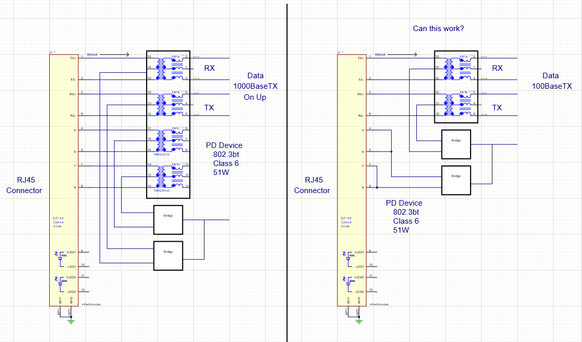
Is it required to have a transformer for all wire pairs in the 802.3bt standard or can I use a smaller Lan transformer for the TX/RX pairs and tie the other together?

Also I would like to understand the current paths on this topology. A popular chart says that the maximum current for type 3 4PPOE  is 600mA per pair. What does this look like on a diagram?

This is a diagram of what I am thinking of.

  • Hello Bruce,

    So POE++ and 802.3.bt are not the same standard. You mention both in your post, which one are you designing for?

    The TPS2372 is a powered device, so i cannot comment on the availability/options of integrated magnetics for the data. 

    As for the requirement, 802.3.bt is meant to support 100baseTX. When you say you want to tie the pairs together, where do you intend to tie them?

    The pairs are tied together after the rectifier. 

    if you mean to tie them together before sending the power over the wire, that would result in more power loss in the cable and probably require a higher class. I am not sure if  PSE can even support that. .bt PSE's can support two pair if it is sending .at or .af power levels..

    Additionally, why could you not send data over two pairs and power over four?

    If this post answers your question, please indicate so by marking this thread as resolved. Thank you.


    Regards, 


    Michael P.

    Applications Engineer

    Texas Instruments 

  • Michael,

    I have read documents online that equate POE++ and the IEEE standard as the same. 

    (ex: www.analog.com/.../jumpstarting-ieee-802-3bts-poe.html)

    I take it that POE++ is used to describe anything above the 802.3at power levels - 802.3bt being a specific standard.

    I uploaded a diagram that shows what I am describing. In Type 2, 2 pairs are used to send power. Two pair are for data and power, and the other pairs are "spare" and are tied together at the RJ45 Jack. -  all pairs  are rectified.

    In Type 3, all 2 or 4 pairs carry power otionally, and all designs I have seen terminate at the PD side at transformers before being rectified. In a 100BaseT system these transformers are not used to pass data so they only there to hook up the "spare" pairs.  

    My example depicts sending data over two pairs and power over all pairs as you pointed out. How these should be terminated is my question.

    Also, gicen a 4 pair power system, I am trying to understand how the currents travel through each pair and at what level. 

  • Hello Bruce,

    IEEE802.3.bt and POE++ are not the same. This is a misconception. Our team has members who helped write the IEEE802.3.bt standard, and are members on the Ethernet Alliance committee. The main differences are that the PoE handshake is different, the MPS current level is different, and the power level of the classes are different. So Class 5 power of 802.3.bt and POE++ are not the same.

    I would be careful reading about non-compliant standards on the websites of the companies that wrote them..

    I reviewed the circuit drawing you sent me, and I think it is possible but I have some reservations. First is that 4 pair power must be used for 802.3.bt, so it will go through all four pairs. 

    Second, the PSE can do detection through either pair sets. However, the impedances between pairset A and pairset B will be different, so I caution you that one pair set may not pass detection. If a particular PSE only detects on one pairset (as some software feature), it could potentially never power up. 

    Third is that 802.3.bt power is supposed to be balanced between the pairs, and now that the impedances are changed, it might affect the PSE. 

    So technically yes you can try it but these are my reservations. 

    If this post answers your question, please indicate so by marking this thread as resolved. Thank you.


    Regards, 


    Michael P.

    Applications Engineer

    Texas Instruments 

  • Michael,

    I did not mean to say that 802.3bt  and POE++ are the "same". And I do not mean to question your position on this. I wished to point out that the term POE++ has been commonly used to refer to 802.3bt. 

    After reading numerous articles on "bt", the word POE++ comes up constantly.  
    Here's one from Hitachi cable: 

    "Q: What is PoE++? A: PoE++ (IEEE 802.3bt Type 3 and Type 4) is a form of Power over Ethernet in which 49 watts (Type 3) or 96 watts (Type 4) of power is transmitted over all 4 pairs of conductors in a category cable. This standard is currently in development."

    Yes, it's outdated, but this is a common statement I am seeing online as I do my research. 

    The confusion in the industry is understandable since POE and POE+ describe 802.3af and 802.3at - it appears that earlier articles use POE++ as a way to describe anything that might be higher power - before the bt standard and yet there is a lot of material out there that links POE++ with the bt standard - which is actually "4PPOE" while POE++ refers to Cisco's "UPOE" (i think). Often one cannot tell when an article was written. This is quite unfortunate. To the extent that nonstandard implementations may be compatible with 802.3bt, I regret using the term POE++ in this discussion - I should have used "4PPOE" instead. 

    FYI, I am not new to POE. I have designed several PD products that are currently on the market that fall under 802.3 Type 1 and 2 range, but I have not designed a PD or PSE POE product of Type 3 or 4, so I am adding this knowledge to my previous experience and wish to apply it to my current 50W project.    

    I believe you may have answered my question regarding the extras transformers - All fours pairs need to be balanced for proper detection. 

    That brings up a couple other questions:

    - If only 2 pairs are used for power and data in type 1 and 2, then why are the "spare pairs" rectified if they do not carry any current - or might they?

    -  I am seeing all 802.3bt design examples where all 4 pairs are being used for data transmission while 802.3af/at design examples seem to use only 2 pairs. I assume this difference is in regard to the ethernet physical layer used: 2 pair for 100Base-Tx and 4 pair for Gigabit Ethernet. In my application, I only need two actual transformers for 100Base-TX data isolation - in a 4 element package, the other two are only used for impedance balancing so I am wondering if I can get by with a cheaper fast ethernet LAN transformer and use cheaper/smaller inductors to balance the other pairs. Might this be compatible in a network?  

    Like this.

    image.png

    Thanks

    Bruce

  • The Wiki article on Power over Ethernet has a table that lists 802.3bt and "4PPOE" and  "POE++" in the same header.

    If this is incorrect, someone needs to change the Wiki. 


  • Hey Bruce,

    I understand there is information out there that is incorrect. This is why i try to explain our involvement in the standard and the Ethernet Alliance to show credibility. I also wanted to explain the differences, since the misconception is that .bt and POE++ is two ways to say the same thing; above 25W of power. 

    To help educate on these topics, we created a video training series. Below is the link to non-compliant high power standards:


    We have other videos on the .bt standard. 

    We rectify the power incase anything nonstandard happens. 

    I cannot speak to the data side of ethernet. I suggest posting this question on our Ethernet PHY team's E2E forum.

    If this post answers your question, please indicate so by marking this thread as resolved. Thank you.


    Regards, 


    Michael P.

    Applications Engineer

    Texas Instruments