This thread has been locked.

If you have a related question, please click the "Ask a related question" button in the top right corner. The newly created question will be automatically linked to this question.

BQ34Z100-G1: Is this design ok?

Part Number: BQ34Z100-G1
Other Parts Discussed in Thread: BQ34Z100, BQSTUDIO

Hi,

after my EVM seems to be broken (another case is open) I decided to use the real board with the BQ34Z100. But this is more worse than the EVM. I can't manage to get the voltage to the real meassured voltage (It shows f.e. 200 mV and meassured it's 10 Volt. And yes, the VoltSel is 1) . Therefore I am guessing, that the engineer maybe made some mistake in the design?

I am not sure if the Ground under the R40 is okay, and I think the R35 and R36 are way to high?

These are the batteries connected to this device:

8 Cell in Series with nominal voltage @ 1.2 Voltage and 800 mAh.

  • Hi Benjamin,

    You likely need to calibrate the voltage, refer to 3.4 of the TRM: 

    Best regards,

  • I've done that, and figured out, that the R35 and R36 is way to high.

    I've configured the both to be at around 240 kOhm. Now I am able to select a prober Voltage Calibration / Divider.

    But besides this, is are there any other mistakes?f.e. is the R40 with 50mOhm still ok or does it have to be a 10mOhm?

  • Hi Benjamin,

    R35+R36 should be calculated so the max battery voltage will apply ~1V to the BAT pin.

    Everything else looks ok.

    Best regards,

  • Hi Nick,

    something is still going wrong and therefor I have tried to compare the Datasheet BQ34Z100 Page 32 Multi-Cell and 5-LED Display and the board design from our engineering. These are the main difference I have found and would like to clarify if it is still ok:

    (BTW. R35 and R36 on our Board, they now have around 236kOhm so the bat can go up to 15275 mV which is more than enough)

    BQ34z100 page 32 our Board
    R2 100K R32 1 M
    R4 165K R33 3.3M
    Q5 BSS84 Q2 ZXMP10A13FTA
    U2 SRN goes to Pack- U7 SRN goes to GND
    U2 SRP goes to Bat-/AGND/GND
    U7 SRP goes to Bat-

    So my questions are:

    1. What's the difference between AGND and GND?
    2. Can it be the same as on our board?
    3. Die the engineer mixed up the SRN and SRP? Or something with the GND?
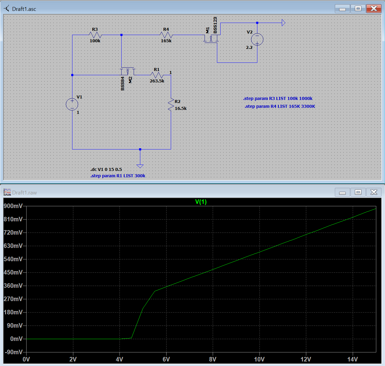
    4. And regards a LTSpice Simulation it seems to be very different between the BSS84 (Q5) and the ZXMP10A13FTA.
      Is it advisable to have the massive drop (picture 1, "copied from manual", if the BAT+ gets too low? Or is the 2nd picture (from our board) better because it linear?


      2nd picture:
  • Hi Benjamin,

    What is the issue you are seeing ? It may be related to the configuration of the device.

    Thanks,

    Nick

  • Hi Nick,

    mainly and in short terms, this: 1663.roomtemp_rel_dis_rel.zip

    In  Words:

    • Charging (Row 4 - 91): Voltage and Current as meassured
    • Relax Period (Row 92 - 4738): Voltage drops from 11960 to 10992 @ 0 mA. But it reflects the meassuring
    • Discharge Period: (Row 4739 - 22771): Current is as maessured, Voltage massivly drops down. 16 mV as BQStudio shows are 8800 mV meassured (Which is 1.1 Volt per Cell)
    • Relax Period (Row 22772 - 27290): 56mV f.e. is 9270 mV, 88mV is 9450 mV, 80mV is 9450 mV

    Therefore I am questioning the board design. Here the config file:7457.OutputFiles.zip

    And I would like to know if this can have an impact on my drop. In this picture I can see that the Ground here is directly connected with the Bat- and is also the ground for the voltage devider and the VSS. On our design the Ground is not connected with the bat- but instead with the SRN PIN, which should only be for the load/charge?

  • Hello Benjamin,

    You should follow the reference schematic for the EVM, just eliminate the sections you don't need (configurable voltage dividers, alert, etc)

    The ground should not be tied to SRN, it should be tied to what's shown on the schematic (SRP, BAT-) Have you been testing on an EVM as well? Are you still seeing these issues with the EVM and your battery pack?

    Sincerely,

    Wyatt Keller

  • Hi Wyatt,

    the picture in the initial post (the first post in this thread) you can see our board design for the Gauge. So it looks like many parts where not build in.

    Just to clarify the part "ground should not be tied to SRN" (and yes we live in germany :) ) The ground MUST be tied to the SRP? Then I can send this info to our outsourced engineer department for not doing the design correctly.

    Yes, I have tested it with the EVM and it worked well until the part, where I tried to programm it with a Firmware and now it's stuck in ROM Mode. Unfortunately the other case with suggestions didn't helped. So I may have a bricked version now :(

    Thanks for your help Wyatt

  • Hello Benjamin,

    Yes, just make sure the grounding follows the EVM example. Ground should be on SRP.

    You should be able to get out of ROM mode by following the bq.fs codes.

    Sincerely,

    Wyatt Kellerhttps://e2e.ti.com/cfs-file/__key/communityserver-discussions-components-files/196/0100_5F00_0_5F00_16_2D00_bq34z100G1.bq.fs

  • Hi Wyatt,

    You're input is not forwarded to our outsourced engineering department. I'll have to wait for feedback.

    And unfortunately your bq.fs File did not helped with my ROM stuck EVM Board. I had to change the first few lines to use the 16 Adress instead of AA and the programming via BQStudion went through without any errors, but it's still in 0x16 Address (ROM Mode). Any other help would be great!

    Best regards,

    Benjamin

  • Hello Benjamin,

    Were you able to just send the final commands in the bq.fs to revert back to firmware mode? You should not need to run the whole file to exit ROM mode.

    Sincerely,

    Wyatt Keller

  • Unfortunately, no. I can successfully read stuff via 0x16, write stuff, but the exit Rom mode  command doesn't work. Maybe there is somewhere a "bit" wrong or the checksum is  incorrect or whatever.

    Is there a way to erase the whole chip and not only a part of it to 0, and reprogram it?

  • Hello Benjamin,

    If programming the default .srec file does not recover the gauge there may be an issue with the gauge and it may not be recoverable, has this happened to multiple gauges or only one?

    Sincerely,

    Wyatt Keller