This thread has been locked.

If you have a related question, please click the "Ask a related question" button in the top right corner. The newly created question will be automatically linked to this question.

LM7480-Q1: Design Quections (Models of ISO 7637-2 & ISO 16750-2 Transients)

Part Number: LM7480-Q1
Other Parts Discussed in Thread: LMR16030, LM5060-Q1,

Hi,

I made a design with the LMR16030 and have been using it for a while. I can say that I had no problems with 12V vehicles. But I started using it on 24V trucks or buses and sometimes I have problems. I cannot detect the net problem on the bus. I used TVS diode and PTC for protection on the input side of the board. I think I am having problems with sudden voltage spikes or dips or etc.(ISO 7637-2 & ISO 16750-2)

Therefore, I think the protection circuit is insufficient and as a result of my research I saw the LM5060-Q1. But somewhere in the forum I came across an article about how the LM7480-Q1 is better.
I have some questions regarding the protection circuit:
1) I produced a total of 20 + 10 pieces of my circuit, whose picture I shared. But as I said, I think I have a problem with a 24V truck or bus. I wonder if this protection circuit (TVS, PTC) is insufficient.
2) If the 1st question is insufficient, do I need to use an IC as I mentioned above? If yes, which one would you recommend?

system requirements:
- 12V, 24V input (car, truck, bus etc.)
- There should be a definite solution to situations such as instant voltage rises or drops so that the system must work uninterruptedly. I think their general name is Models of ISO 7637-2 & ISO 16750-2 Transients.

If there is anything you do not understand please write to me so I can find a clear solution.

Will using LM5060-Q1 or LM7480-Q1 instead of the protection circuit at the input solve my problem?

Regards,

Mehmet

  • Hi Mehmet,

    LM7480-Q1 can be used ahead of LMR16030 in order to obtain immunity from   Automotive Transient like ISO 7637-2, ISO 16750-2 and LV124.

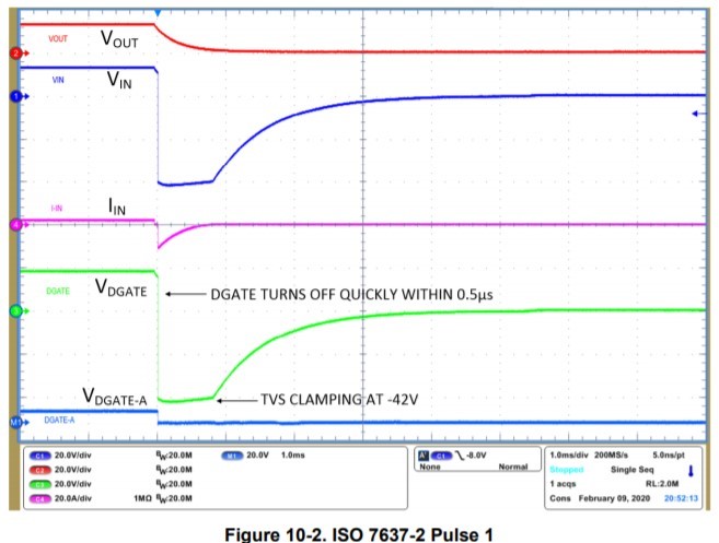
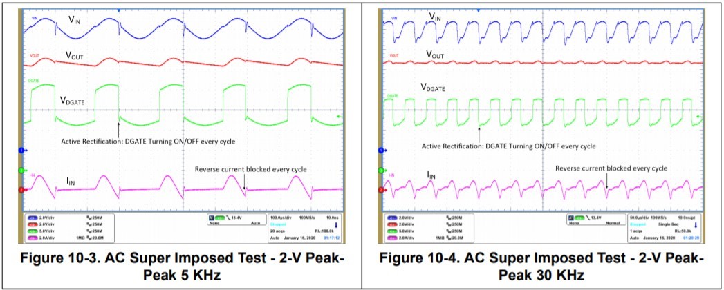
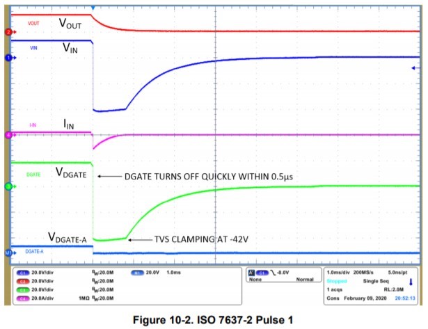
    Please refer to section '10.2 Typical 12-V Reverse Battery Protection Application' in LM7480-Q1 datasheet. You can also see test results for ISO 7637-2 and ISO 16750-2 in datasheet as shown below. 

  • Hi Praveen,

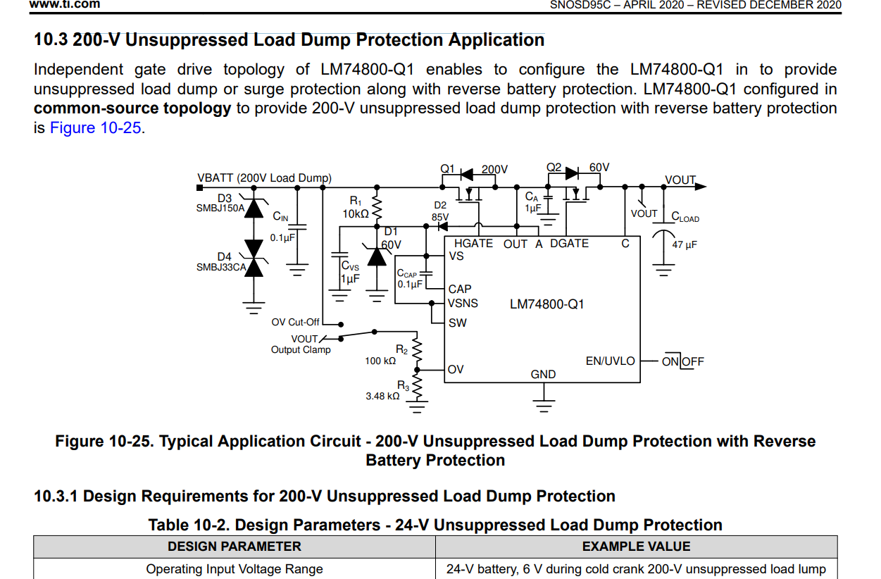
    I was thinking that 10.3 200-V Unsuppressed Load Dump Protection Application would suit me better. Because I need uninterrupted output at both 12V and 24V (car, truck, bus).

     Am I wrong about this? Wouldn't it be a problem if I tried the topology you suggested '10.2 Typical 12-V Reverse Battery Protection Application' on a 24V truck?

    Regards,

    Mehmet

  • Hi Mehmet,

    You can choose common-drain topology (Figure 10-1) or common-source topology (Figure 10-25) which ever better suits your requirement.

    • Both of the typologies provide Immunity to Automotive Transients - ISO 7637-2, ISO 16750-2
    • Common-source topology (Figure 10-25) additionally supports 200-V unsuppressed load dump Pulse 5 A and –600-V 50-Ω ISO-7637 Pulse 1
      • Common-source topology has a bit higher component count compared to Common-drain topology.

    You can refer to sections '10.2 Typical 12-V Reverse Battery Protection Application' and '10.3 200-V Unsuppressed Load Dump Protection Application' in datasheet for more understanding on these typologies.

  • Hi Praveen,

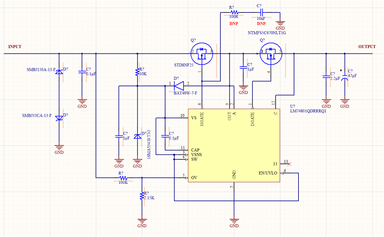
    I drew a schematic on common-source topology (Figure 10-25).

    I mentioned the regulator I used in the output section in my first post. (LMR16030)

    1) I want to see a voltage in the range of 5V-60V at the output.

    2) Considering ISO 7637-2 & ISO 16750-2 Transients, there should be no voltage interruptions at the output. The system I use should be always on.

    Do you confirm the above 2 items?

    Is there any general missing in the schematic? can you please tell me if there is?

    Regards,

    Mehmet

  • Hi Mehmet,

    SMBJ33CA seems to be unidirectional in your schematic. Please confirm again and check if it is bi-directional. The remaining schematic looks good to me. 

  • Hi Praveen,

    SMBJ150A-13-F is  an Single (uni-directional).

    SMBJ33CA-13-F is an Single (bi-directional).

    I think I made a mistake drawing the schematic. i will fix it I think there is no problem other than that.

    Can you answer the 2 questions I asked in the previous post?

    Regards,

    Mehmet

  • Hi Mehmet,

    ISO 7637-2 Pulse 1 is negative voltage transient at input and hence the LM7480x-Q1 will pull the DGATE low disconnecting the output. Hence in this case you can expect the output to drop. 

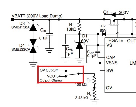
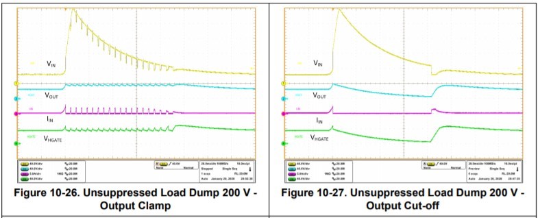
    For ISO 16750-2: 200-V unsuppressed load dump Pulse, in case you want the output to be present (like in figure 10-26) during the transient, you will have to connect the OV pin to output. In case you connect OV pin to input, you will see result as in figure 10-27 where the output is cut-off during the transient. 

  • Hi Praveen,

    Thank you for the answer. I set the OV to connect to both input and output. I will get a prototype this way.

    If there is a problem while testing, I will contact again. If you have anything to add, please write to me.

    Regards,

    Mehmet