This thread has been locked.

If you have a related question, please click the "Ask a related question" button in the top right corner. The newly created question will be automatically linked to this question.

UC3843: Removing decoupling caps / series resistor

Part Number: UC3843

Hey team,

Got an odd one for you here:

The datasheet calls for 2 decoupling caps, a .1, and one that is 10 times greater than the switching FET’s gate charge. The datasheet ALSO calls out for a series resistor on the Vcc pin. Does TI have any documentation on the effects of not including these components, I.E. will it significantly change the lifespan of this device? MY guess was that those components purely for EMI/EMC, and or self-heating but I wanted to reach out to see your thoughts on this.


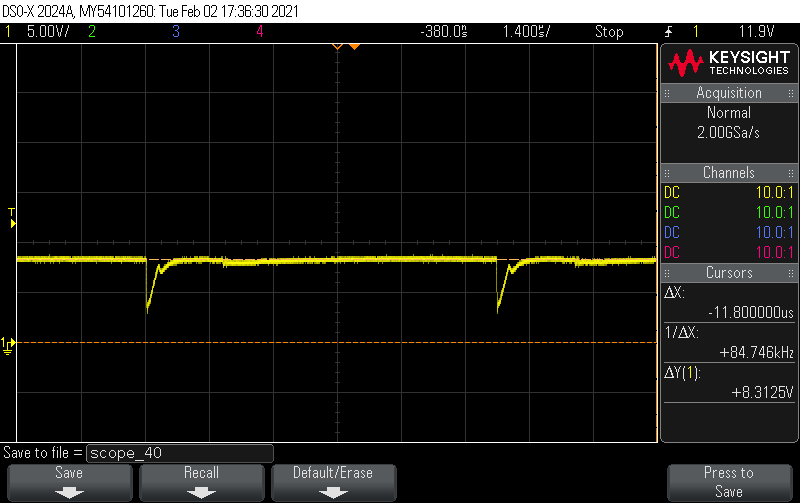
What prompted this, was between two board revisions the series resistor was added, and the decoupling capacitor is now connected through a resistor, and when the device switches, the power drops 5v, which is below the turn off threshold voltage (attached) and we are trying to avoid another board spin before CE testing. As of now, the board works, and the radiated emissions seems to be OK. Do you believe these dips is enough to cause trouble to the Chip?

  • Hi Cameron,

    I'm not sure about the long term reliability of the controller but the guidance in the data sheet should be followed as close as possible. The 0.1uF capacitor on VCC is a for decoupling potential noise but the larger parallel capacitor (10x MOSFET gate charge, C=Q/V) is important because it supplies the necessary charge to efficiently drive the MOSFET VGS. Without this capacitor, you see the notches on VCC. You should also be questioning the drive voltage on the MOSFET VGS - does the pulse look sharp or does it sag and change amplitude across the top? Driving a MOSFET this way, you are not fully enhancing the RDS(ON) and this is not good for efficiency and long term reliability of the MOSFET. I would recommend to kluge the two caps in place, carry out the EMI test and respin the PCB afterward - there may be additional component changes/additions that fall out from the EMI testing.

    Regards,

    Steve M