This thread has been locked.

If you have a related question, please click the "Ask a related question" button in the top right corner. The newly created question will be automatically linked to this question.

BQ25505: No nVB_SEC_ON signal. Stays high

Part Number: BQ25505

Note that R1 connections to Pin 11 and Pin 12 are reversed and have been modified on PCBA.

It seems that no matter what I do with the input voltages J1 to pin 2 and through L1 I cannot get the nVB_SEC_ON signal Pin 9 to go low. 

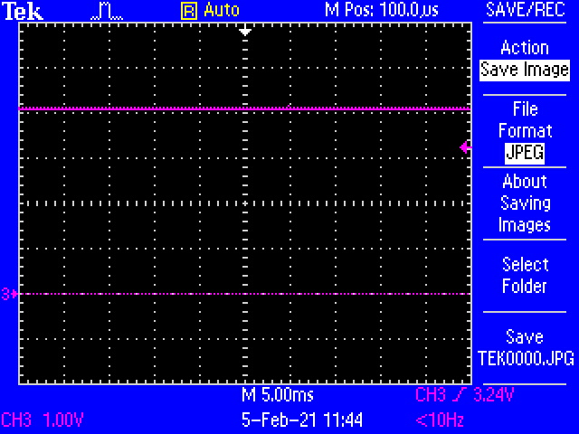
I do see that the device is pumping up the VBAT_SEC pin to 4.19 Volts

I attempted to short pins 18 and 19 per the previous suggestion.

Any suggestions on getting this pin to drive low?

D

  • Hi D,

    /VB_SEC_ON is controlled by VBAT_OK.  To what voltages are your OK and OK_HYST resistors setting the VBAT_OK thresholds?

    Regards,

    Jeff

  • Hi Jeff,

    Thank you for the reply. 
    I thought I had attached the schematic but it did not get through.

    Here are the resistor values

    Rov2 = 7.5Meg
    Rov1 = 5.76Meg
    Rok3 = 887K
    Rok2 = 6.98Meg
    Rok1 =  5.36Meg

  • Hi D,

    The schematic looks okay.  Is VBAT_OK changing state at the correct voltage?  If not, can you provide a waveform similar to datasheet waveform fig 20 on page 23?  The only other issue that I have seen is parasitic resistance in parallel with multi-megaohm resistors changing the effective resistance as explained in datasheet section 10 page 29.  

    The datasheet block diagram says that the power for the /VBXXXX drive pins is an OR from VBAT_SEC and VBAT_PRI.  Can you easily connect VBAT_SEC to VBAT_PRI and see if that makes a difference?

    Regards,

    Jeff

  • Well I think we have some improvement but still have a bit of confusion.

    1) Here are the images of the various wave-forms

    this is VBATT

    This is the power supply that is imitating  the solar panel input 

    This is the Boost node after the input inductor

    VDIV

    VSTOR

    So now things are moving along but the output signal to turn on the P-FET is still high

    Per the suggestion on high value resistances I lowered all the sense resistors by a factor of of 100 and things seemed to be functioning although the output from the solar cell input would drive the BATT to 6.25 volts when the input to the battery was driven by a lab power supply (single quadrant type ie no ability to sink current).

    Turning off the Solar input power supply and replacing the (Battery) lab power supply with an actual Li-Ion battery we get this waveform on the VSTOR line 

    If I turn on the Solar input power supply it appears that everything starts working again with VSTOR going just a few mV above the battery terminal voltage and it seems to be charging the battery as expected.  I can remove the Solar in voltage and it appears that the system stays running unless a remove and reattach the battery?

  • Hi D,

    Just to confirm, you are not putting an input voltage (power supply or solar panel MPP) that is higher than VBATOV, correct?  This is a boost only charger.  It can't buck down a high input to a low value.

    The second pulse of the VRDIV waveform should be 2/3 of your VBAT_OV set point.  If lowering your resistance values improved operation then one issue is parasitic resistance from solder flux.

    Regarding the 6.25V, that is bad.  The output can't withstand more than 6V.  The other known issue is noise into VSTOR that is not getting filter by the 0.01 or 0.1uF capacitor from VSTOR to GND.  This noise can also cause a problem with the VSTOR regulation.  That capacitor must be as close to IC as possible as shown in datasheet layout example.

    Regards,

    Jeff


  • I do understand this is a boost only converter and the input voltage is less that battery voltage and seems to do it job just fine as depicted in image 3 above.

    Here is a picture of the layout. The caps are right there as close as is practical  Resistors and Caps are 0603. C5 and C6 are the capacitors in question

    My biggest concern now is the failure to start with only a charged battery and the VSTOR waveform at about 1 volt and a 1 Second period. as shown in imagee 5 above. Once I power the unit from the "solar in" the output of VSTOR seems to come back to battery voltage and the nVB_SEC_ON will go low. I can remove the MPPT input and the unit appears to continue to work. If I remove the battery however the voltage rises to over 6 volts.

    Kind Regards.

  • HI D,

    If I understand correctly, nVB_SEC_ON is working correctly now?  But VBAT_OV is still too high.  The only 2 know issues for the charger to be out of regulation are the 1) the parasitic resistors formed by solder flux, which you mitigated with smaller valued resistors and 2) the placement of the 0.1uF capacitor to filter out switching noise, which you placed correctly.  The pulse waveforms are showing VSTOR = 4.05V and 2/3*VBAT=2.7V, which are within tolerances.  

    When you insert a charged battery, the VSTOR and VBAT_SEC voltages need to be close <100mV.  If not, the PFET between VSTOR and VBAT_SEC will not close until the input charges up VSTOR above 2.0V.   The charger is in cold start until then so charging up the VSTOR cap may take some time.

    Regarding the rise to 6V with no battery, is the boost converter still switching at LBOOST and trying regulate to 6V or this is simply an overshoot due to only 10uF at VSTOR?  If only overshoot, adding more capacitance at VSTOR should prevent the overshoot.

    Regards,

    Jeff