Hi,
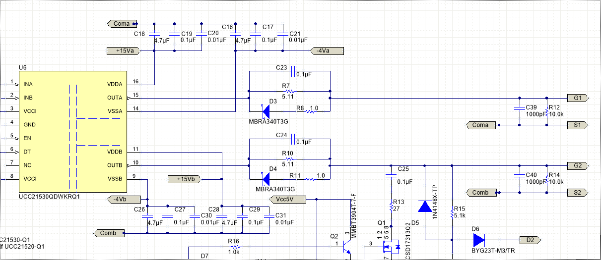
I have seen a 10kOhm resistor between Gate and Source (see R14 and R12 in the attached fig from tidue55b.pdf), but I cant figure out why the resistor is there. My guess is because measuring purposes without a MOSFET being there.
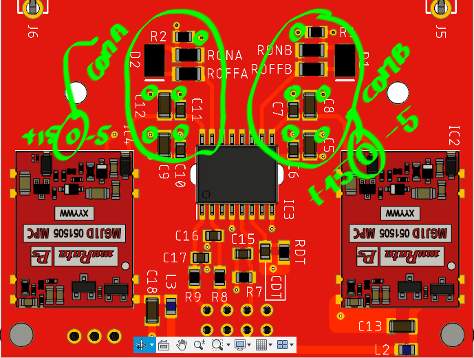
I am using a +15, -5V dual output configuration for the UCC21520.
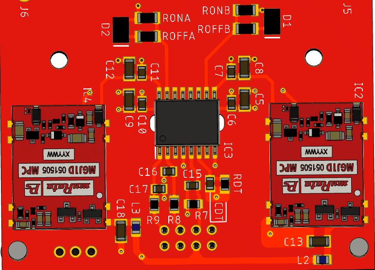
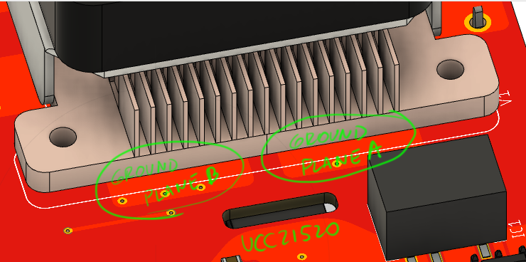
Second question, will a ground plane in coma (S1) or comb (S2) help to reduce noise in the gate trace form OUTA or OUTB to the SOURCE of the mosfet? I couldn't find PCB recommended guidelines for dual output sources feeding the UCC21520. In some how, RON, ROFF and the Diode are above the ground plane connected the the source as a 0-V referred to the source pin of each mosfet.
Thanks,
Pablo