This thread has been locked.

If you have a related question, please click the "Ask a related question" button in the top right corner. The newly created question will be automatically linked to this question.

TPS56637: Unexpected behavior After Over current protection

Part Number: TPS56637

Hi Team,

When checking over current protection of TPS56637, it seems that TPS56637 gets unexpected behavior as attached(See here).
Have you seen this issue before?

[Experimental setup]

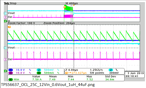
- Output is set to 0.6V or 0.9V
- Load current was slowly ramped up by CC mode electric load to OC threshold
- After TPS56637 gets OCP, voltage was drop and got the issue(Large ripple and draw current limited to 2~3A)

TPS56637 can no longer draw a large current until I drop Vin below UVLO.

Regards,

Takashi Onawa

  • Hi Takashi,

    I saw the waveform that you uploaded. This kinds of waveform are familiar in some issues, but I can't judge with enough information for analysis.

    Could you please provide the schematic and the SW waveform under this situation? If the inductor current waveform could be captured and provided, that would be better.

    Regards,

    Andrew

  • Hi Andrew-san,

    Sorry for my slow response on this.

    I got some data(SW node waveform and layout) from them, could you check those and advice me what I should ask them next? (Please find internal link : here)
    But I think the waveform looks strange so I’m just asking them to take the capture again.

    By the way, do you have any capture showing voltage transition when ramping up Iout and getting OCP?

    Regards,

    Takashi Onawa

  • Hi Takashi-san,

    Thanks for your reply. First, I agree with you that I think the data isn't correctly measured by the scope. But if I assumed the scale of the two waveforms are same, I think the waveform shows that the SW frequency are almost same in those two conditions, but the voltage levels are different. Maybe the input source voltage changes after OCP due to some reasons.

    So please double check with customer about the waveform...

    Here I upload a OCP waveform of TPS56637 as attachment.

    Regards,

    Andrew

  • Hi Andrew-san,
    Thanks for sharing the capture during OCP.

    I have a couple of question regarding OCP behavior of TPS56637.

    1. Can you tell me the interval of the hiccup pulse output?
    2. In the waveform you shared it looks like the SW is stopped, why is that, is the Electric load stopping working?

    Here is my understanding and I have some unclear point its behavior. Please point out and comments if my understansing is not correct.
    According to the datasheet, TPS56637 behaves as following in OCP event.

    Get cycle by cycle OCP and output will be slightly degreased due to forced Low side FET ON and constant high side ON time.
    When the output voltage falls below 65% of the set value, the device shifts to hiccup operation for 25ms after a 0.25ms deglitch time. (I didn’t get any information about hiccup pulse interval in the datasheet, Is that 25ms?)
    If the OC condition has not removed after 25ms, what’s happen?
    Regards,

    Takashi Onawa

  • Hi Takashi-san,

    1. It's said in the datasheet that "hiccup time" is 25ms, I think which corresponds to the interval of hiccup pulse as you mentioned.

    2. The SW pulse stopped because the UV protection is triggered. When inductor current is larger than the OC set value, first the OCP will be triggered. During off-time in OCP, the low side Mos will keep turning on until the inductor current valley (sensed from voltage of low side Mos Rdson) equals to the set OC value. Then the on-time will start and it's fixed to a short time. And off-time will start again.. This kind of protection is the so-called "cycle by cycle" protection.

    With this kind of OCP, the inductor valley current is limited to OC value. Also the inductor current ripple will be certain value since the on-time is fixed. So the average inductor current is limited as certain value in the cycle by cycle OCP. Since the output current Iout>IL, the output cap will be discharged to provide the output current and the Vout will decrease. After the output voltage falls below 65% of set value, a deglitch timer will be triggered. If the under voltage situation last longer than 256us, then the UV protection will be triggered. During UV protection, SW is stopped. That also starts the hiccup process, converter will try to restart after 25ms hiccup time.

    3. If OC condition isn't removed after 25ms, converter will restart with OC loading, which is same as the procedure to power up with OC loading. During softstart time, IC will try to charge the output cap but the output voltage increase is limited due to the OC protection limit. After softstart time, the UV protection will be triggered. After 25ms, next hiccup restart will happen again.

    If there's anything unclear, please point it out and I'll try my best to give explanation.

    Thanks,

    Andrew 

  • Hi Andrew -san,

    Thanks for your explanation. I almost understood how TPS56637 behave in OCP condition.

    If possible, can you get measurement data that shows that the hiccup operation is taking place after the load current is ramped up and applied to the OCP?

    It looks the capture you shared shows hard short event behavior, Our customer is checking OCP under gradually increasing load current, so I would like a reference on how it behaves under the same conditions.

    Regards,

    Takashi Onawa

  • Hi Takashi-san,

    You can refer to the waveform below.

    The 1st waveform shows the load current is ramped up fast and triggers the OCP. The green curve is the inductor current. When the OCP is triggered, the inductor current is limited at certain value with the cycle by cycle protection.

    Then the output voltage (blue curve) drops below the lower threshold for under voltage protection. After the 0.25ms deglitch time, the under voltage protection is triggered and IC shut down, where you can see the output voltage and inductor current gradually drop to zero.

    After hiccup time, ic will try to restart, as shown in the figure below.

    There's one thing to explain: the current increasing slew rate before OCP triggered in the 1st waveform might be a little bit higher than the customer's case. But the result and behavior after OCP triggered should be almost same.

    Thanks,

    Andrew

  • Hi Andrew-san,

    Thanks for your kindly and excellent supports on this. Sorry for my slow response.

    I could understand how TPS56637 behaves after OCP protection, so let me close this thread once.

    I might be back if my customer issue will be not solved.

    Regards,

    Takashi Onawa

  • Hi Andrew-san,

    Sorry, let me request one more data on this.

    It seems that they can see same behavior in Vout 3.3V condition but it was not same at lower than 0.9V output condition.
    Do you have similar capture when the output is set to lower than 0.9V?

    I wanted to check that point on my bench tomorrow but it seems that EVM has not shipped from TI.com due to some reason...

    Regards,

    Takashi Onawa

  • Hi Takashi-san,

    FYI. 0.6Vout OCL waveform.

    Thanks,

    Lishuang