This thread has been locked.

If you have a related question, please click the "Ask a related question" button in the top right corner. The newly created question will be automatically linked to this question.

TPS40211: RC pin to sync with another controller

Part Number: TPS40211

Hi Team, 

We would like to seek your inputs on this.

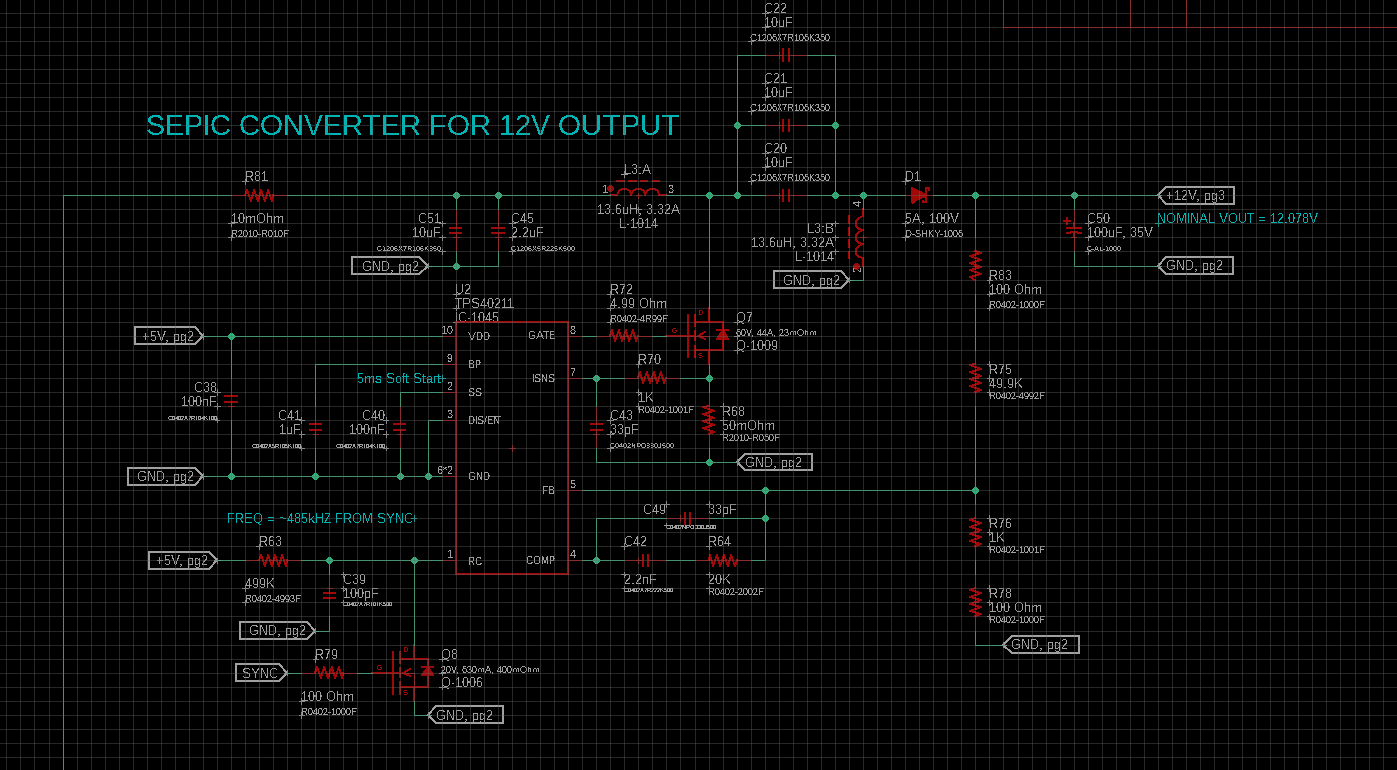
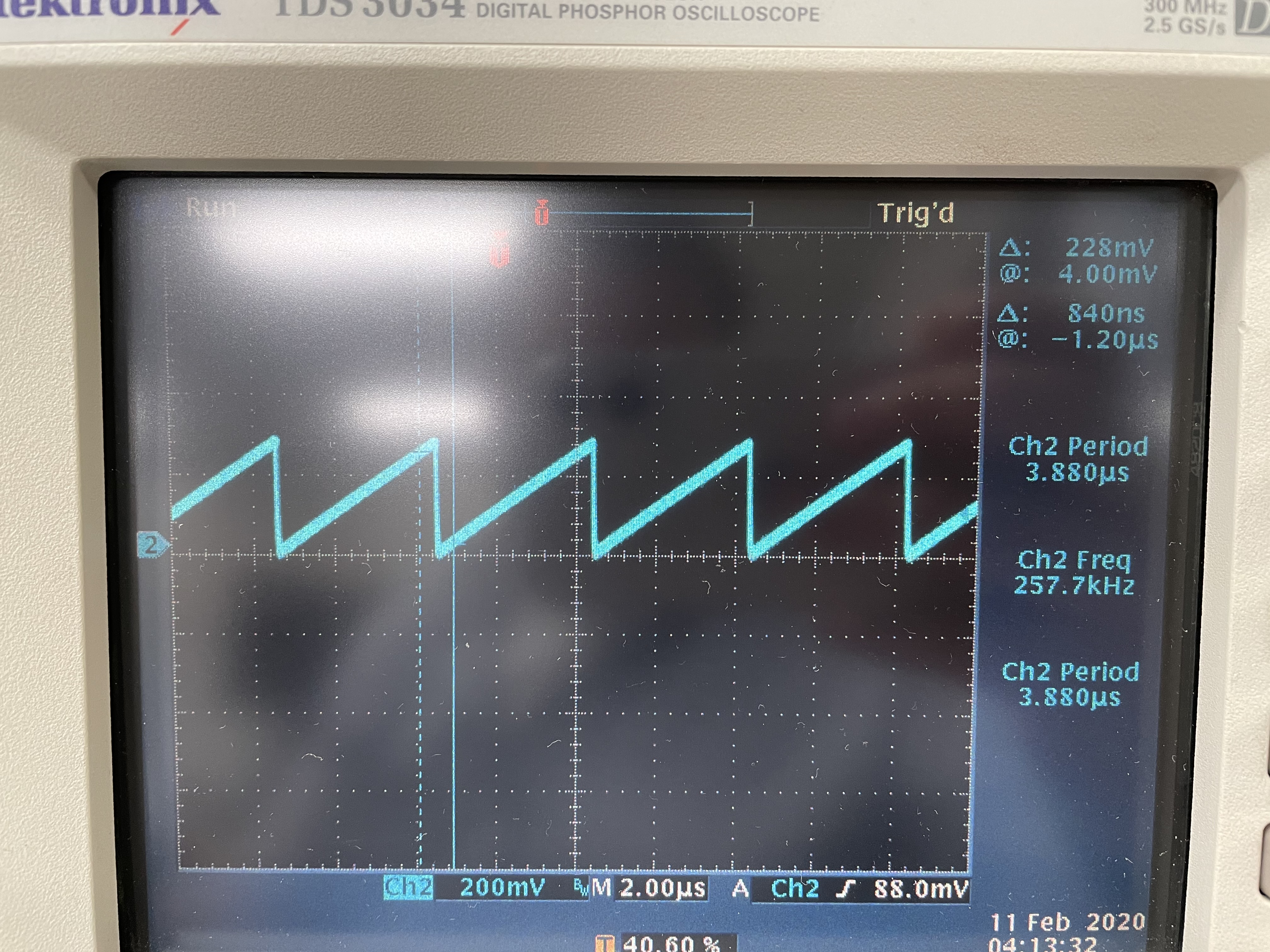
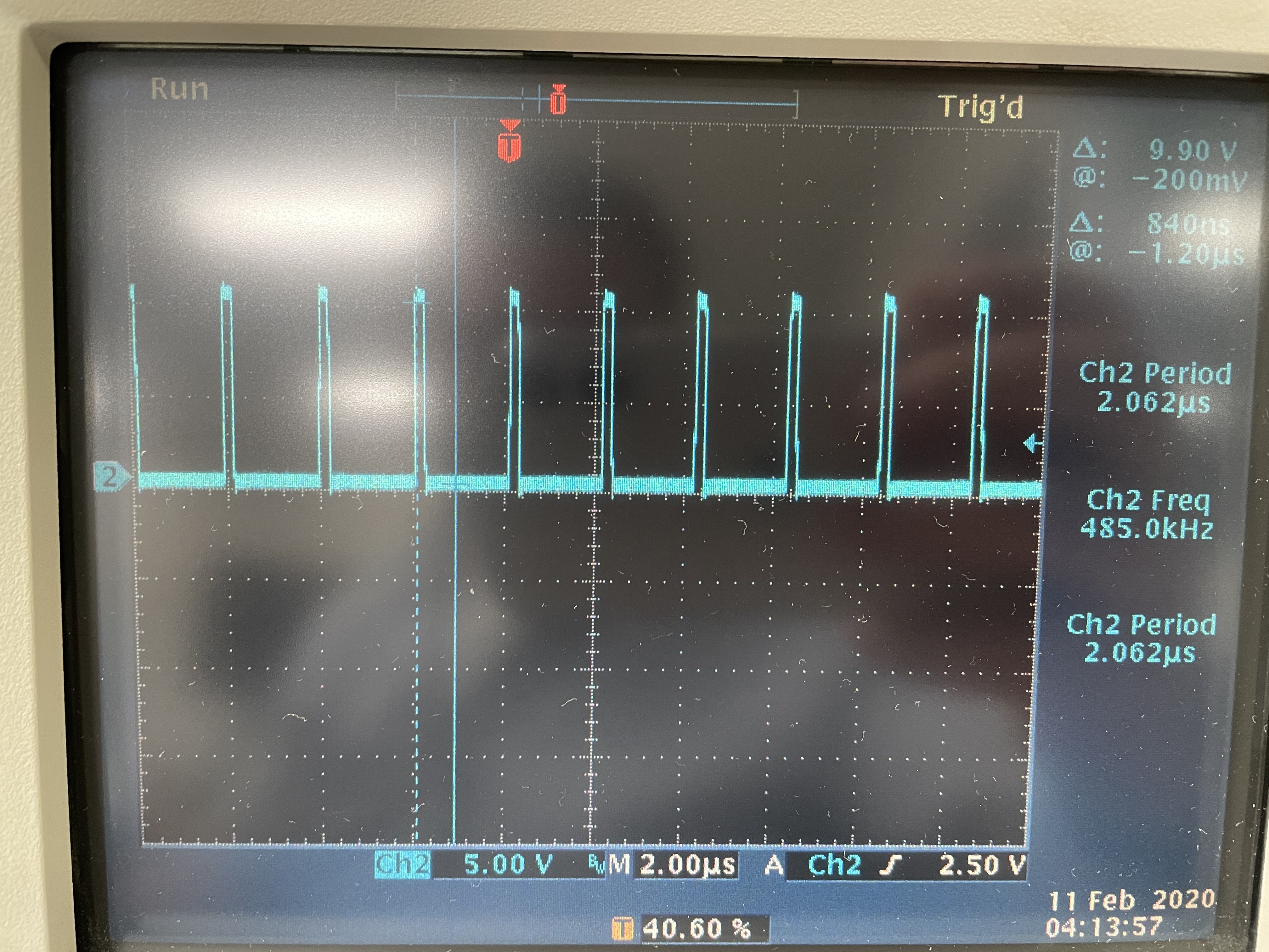
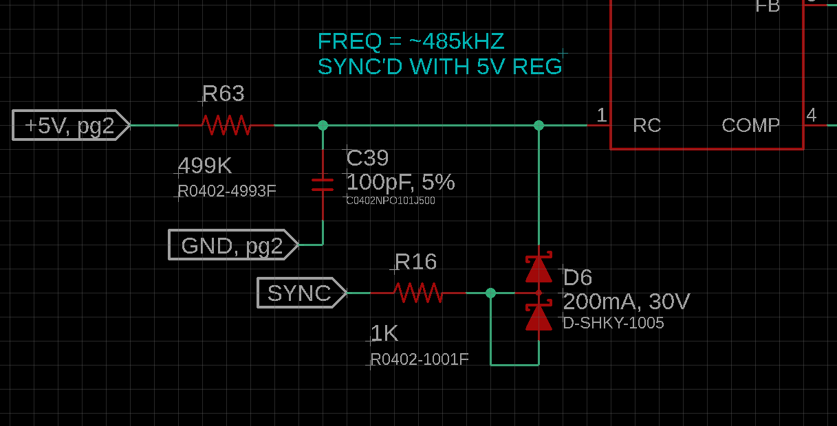
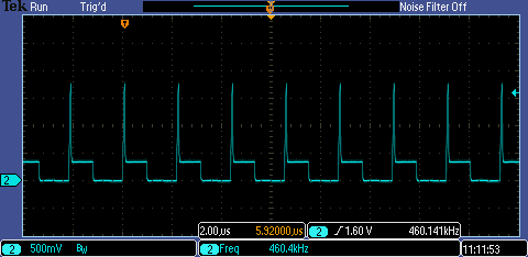
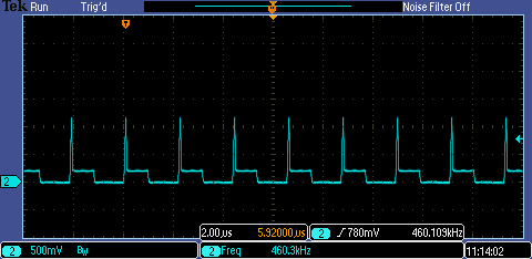
Trying to tie in the RC pin to sync with another controller but is having an issue. without the sync connected, the converter runs at 260kHz and the RC signal looks like a ramp where it goes from 0V to about 300mV. when it connect the sync via an n-channel mosfet that is running at 485khz the RC pin will actually go negative about 150mV and it looks like the ramp is almost inverted.

Thank you very much in advance.

-Mark

  • Hi Mark,

    Thank you for reaching out.  It is should not to go negative unless the circuit introduces some inductance by the FET.  Also, If the FET is not and off  fast, the ramp may look like inverted.  You just need a small signal FET there and also check your sync source driving capability.

    Thanks,

    Youhao Xi, Applications Engineering 

  • Hi Youhao, Thank you for responding.

    According with my customer, The FET they are using is a DMG1012T-7 from diodes inc. It is pretty fast where the turn on delay + rise is 12.5ns and the turn off delay+fall is 39ns. As for the signal driving the FET they validated the waveform and also tried hooking up a waveform generator where they varied the frequency and duty cycle but the RC pin was still going negative.

    Hoping for your assistance.

    -Mark

  • Hello Mark,

    Please share the waveform on RT without and with the FET. In addition, please send a schematic how the FET is connected.

  • Hello Brigitte,

    The signal coming in on the sync signal to Q8 is running at ~485kHz at about 45-50% duty cycle.  There is a note on the datasheet about the duty cycle but I have even hooked up an arb to vary the duty cycle from 5% all the way up to 50% with the same result.

    The controller is configured as a sepic converter.

    Here is the waveform of the RC pin without the sync signal hooked up (Q8 gate is tied to gnd). 

    Using the arb, I set the frequency to 485kHz with a duty cycle of 10% and I feed that into the gate-source of Q8 and to confirm is what I am reading on the gate (note the voltage amplitude is higher on the scope because I didn't have a 50ohm termination on the output of the arb. I did notice the vgs of the signal mosfet is ±6V so I had the mosfet replaced and I even tried reducing the arb voltage and I got the same result)


    With the arb signal running or even the default sync signal hooked up we are getting a waveform that looks like the image below on the RC pin.  When Q8 turns on it returns to ~0mV but when Q8 is off it falls to -300mV and then starts to ramp back up.

    Thank,

    Brian Long

  • Hello Brian,

    Please give me some days to check this in the lab.

  • Hi Brigitte, do we have an update for this?

    Thank you.

  • Hello Mark,

    Sorry for the late response. We have seen a similar negative voltage when synchronizing with a MOSFET. The parasitic capacitance of the MOSFET causes this negative voltage. Please either use a bipolar small signal transistor or the diode method given as well in the datasheet to stay within the absolute maximum ratings of the device.

  • Hello Brigitte,


    Thank you for looking into the issue.  I have tried using a BJT (PN: MMBT3904T-7-F) and the waveform was identical to using the N-Channel MOSFET.  The diode solution works but it doesn't seem like a great idea because I am loading down the sync signal that goes to other devices.  I had to isolate the sync signal to the TPS40211 with a 1K resistor so when it resets the RC capacitor it wasn't a dead short on the sync pin.  Now the waveform goes up to about 2V then the RC capacitor reset occurs and pulls the signal down to about 300mV (while the sync signal is still high) then after the sync pulse goes low the RC pin also goes low.

    Just to clarify it is sync'd but it doesn't seem to be a great solution.  I changed the 1K in series to 2K and the amplitude of the peak went down to about 1.2V.  I then changed the value to 4.99K and it no longer works.  Instead it just looks like it keeps trying to reset the RC pin but there is not enough hysteresis to keep it reset and it just oscillates while the sync pulse is high.  The 1K seems like a viable solution but to draw 5mA on the sync pulse means I should probably buffer it.  It is just unfortunate that it didn't work the way the datasheet said using a MOSFET or BJT.


    1K in series with diode: 

    2K in series with diode: 

    4.99K in series with diode: 

    Thanks,

    Brian Long

  • Hello Brian,

    Normally with a small signal bipolar transistor you will observe a negative voltage, but it should be a lot less than with a MOSFET. How much negative voltage did you observe with the bipolar transistor?

  • Hello Brigitte,

    The BJT went about 120mV negative which is slightly less than the MOSFET.

  • Hello Brian,

    120mV negative is less than half the abs max rating, so I think this would be the best solution for your problem.

  • Hello Brigitte,

    The signal never goes positive though so it doesn't actually sync properly.

  • Hello Brian,

    Strange, let me check again in the lab and send a measurement.

  • Hello Brian,

    Sorry for the wrong direction. I did not find a good solution other than the diode up to now.

    Best regards,
    Brigitte