This thread has been locked.

If you have a related question, please click the "Ask a related question" button in the top right corner. The newly created question will be automatically linked to this question.

LMR70503EVM: LMR70503EVM evaluation boards don't work at -5V as advertised

Part Number: LMR70503EVM
Other Parts Discussed in Thread: LMR70503

Purchased a LMR70503EVM evaluation board for testing various loads with this device at -5V. The product was designed and sold by TI to produced several output voltages using a select jumper based on the LMR70503 chip. Per the documentation, no jumper should produce -5V at the output. When I tested the board without a jumper and a 3.3V input (then later at 5V) with no load on the output, the output would only reach about -3.6V and was not stable. When placing the jumper on the -2.5V that seemed to produce a stable -2.5V, as well as lower output voltages (-1.5V and -0.9V) seemed to work too.

Thinking this board was just faulty, I purchased a second unit. The second board behaved exactly as the first, and would not produce a stable output at -5V.

I created a ticket to TI Customer Support Center, asking why this product doesn't work as advertised, and here is what they said. "I just said our customer support center can't resolve your problem instead of the whole TI. Since we do not have the simulation condition we can not resolve some practical problem such yours. However on E2E Forum there are many developing engineers who can handle the difficult problems. Therefore posting on E2E forum is the best way to resolve your question." They seem to only offer help if you have a simulation of your design, but it's not my design and I couldn't seem to get that across to them.

Has anyone else seen this issue?

Shouldn't I expect TI to answer a question about their own design?

  • Hello Sir Clark,

    Thank you for posting.  Could you share some scope pictures showing SW, VIN and VOUT?  Please zoom into show a few switching cycles, and also zoom out to show ~100 cycles on your oscilloscope screen?  When sharing, please tell which scope trace is which signal, and also your Vin and load conditions.  Please test with both 5Vin and 3.3Vin.

    Thanks,

    Youhao Xi, Applications Engineering

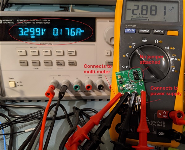
  • As you can see from the picture, there are only two connections (plus grounds) to the TI designed LMR70503EVM board, the input from the power supply is set to 3.3V and the readout from the muli-meter is only at -2.9V but should be closer to -5.0V because there is no jumper installed. There is no load (other than the multi-meter) on the output. What is the purpose the requested scope captures, since if anything wrong is observed then I'm only going to point out (again, and again) that this is a TI designed board? Both boards are out-of-the-box tested with no modifications.

  • Hello Sir Clark,

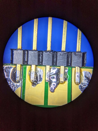
    I am sorry that you have issues with these EVMs. On the EVM on the picture, you soldered some connectors to the metal areas. I do not expect that this is causing any problem, but it would be interesting if you saw the same behavior before you soldered these pins or if it is only observed after you soldered them.

    I have to mention that every EVM is tested before it gets stocked, so it is strange that you received 2 boards which seem not to work.

  • Brigitte, thanks for the quick response. Yes, I soldered a 5-pin connector to the first unit so the board could be inserted into a solderless protoboard. See uploaded image. Note the 3 center pins are all grounds (so that very center pin doesn't get used), and outside pins are VIN and VOUT. The microscope can magnify much more than that image, and there are no solder bridges to ground observed on the outside pins. Also, this board behaves exactly the same as the other, which both work at -2.5V and below. It's only at -3.3V and -5.0V that both boards fail to regulate. 

    Yes, it would be my dumb luck to get two bad units. The LMR70503 chip is really the perfect fit in our present design (size constraints), so I really wish this issue could be resolved.

    You mentioned that every EVM is tested before stocking, but at all output voltages, or just one? If that was the case, then maybe that explains the quality issue. Only guessing here.

  • Hello Sir Clark,

    Thank you for the clarification that you soldered the pins only to one of the 2 boards.

    According to the test report, all voltages are tested on all boards. I took one of the boards that I have and checked that it is outputting 5V when the input is at 3.3V. In addition, I requested another board from the stock to check if there is a general quality issue with these, but shipment will take around a week.

    Could you do me a favor and check the output voltage with a scope?

    Could you as well check if the behavior changes when you add the 3.3V to the EN pin?

  • Hello Sir Clark,

    I received the EVM from stock and it works properly. I do not have any idea why your 2 EVMs do not work as expected. I am sorry, but please try it again.

  • Your suggesting I purchase a third unit and try again? If so, no thanks, I'll just change the design to a different part. Linear Technology seems to have some good choices to test out.

    Thanks for all the support. I guess I'll mark this issue as resolved although that feels wrong.