This thread has been locked.

If you have a related question, please click the "Ask a related question" button in the top right corner. The newly created question will be automatically linked to this question.

TPS28225: Outputs in PSpice Simulation always LOW

Part Number: TPS28225
Other Parts Discussed in Thread: UCC27524,

Hello 

I created the following simulation circuit:

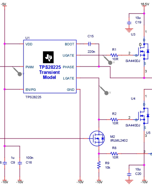
The problem is that the output signals UGATE and LGATE are always at -10V. The PWM signal is correct and changes between -10V and 0V. Any ideas what the problem could be?

Thansk for your help.

Best regard

  • Hello Robin,

    Thank you for providing the simulation circuit schematic, that helps address the questions.

    The driver spice models are usually configured where the driver ground pin is expected to be at the circuit ground reference. I have encountered this before in customer simulations and was able to resolve.

    You will need to configure the circuit where the driver ground is connected to ground of the simulation circuit, and change the other bias voltages accordingly.

    Basically add 10V to all the voltage reference points. What is the amplitude of the PWM signal provided to the driver in your circuit? Make sure the PWM is referenced to ground when you level shift the voltages as suggested.

    Confirm if this addresses your concerns, or you can post additional questions on this thread.

    Regards,

  • Hello Richard

    Thanks for your fast reply. You are right! After adding 10V to every voltage it works as expected. 

    But in real life you also do not see any problems with the GND of the TPS beeing at -10V and VDD at -5V? I would also do the same thing with the UCC27524 with -10V and 0V. Do you see any risks doing this?

    Best regards

  • Hello Robin,

    It is good to hear that the suggestion solved your simulation issues.

    For your question on your actual circuit conditions. The drivers can work with the IC ground pin referenced to a negative, or positive, voltage. But make sure that the driver input signals have the amplitudes referenced to the voltage potential that the driver ground is referenced. In the case of the TPS28225, the PWM low should be -10V and high will be -7 to -5V for example.

    The same is true with the UCC27524.

    If you have more questions you can always open the thread again.

    Regards,