This thread has been locked.

If you have a related question, please click the "Ask a related question" button in the top right corner. The newly created question will be automatically linked to this question.

LM51561-Q1: Feedback compensation

Part Number: LM51561-Q1
Other Parts Discussed in Thread: LM5155

Hello,

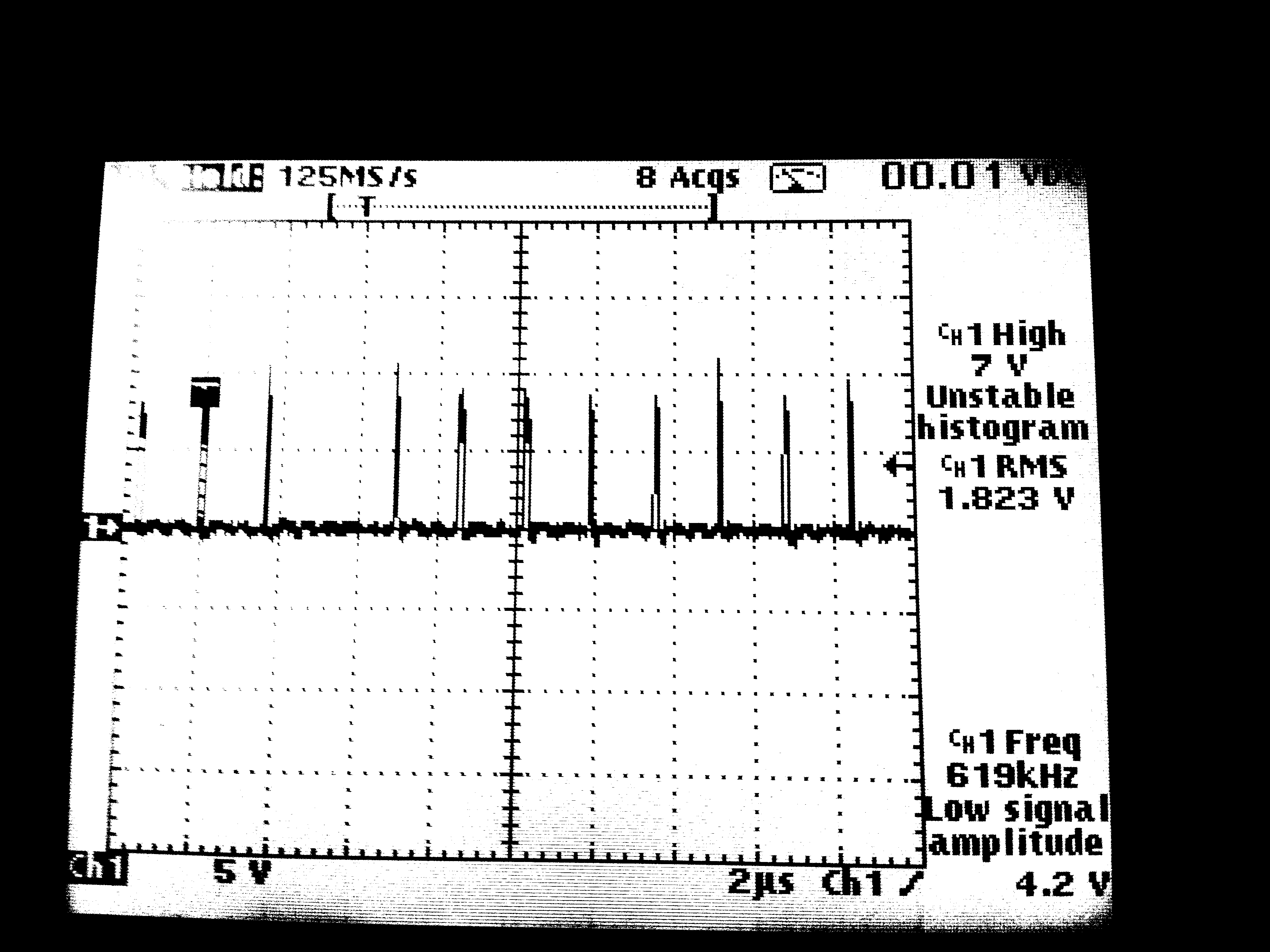
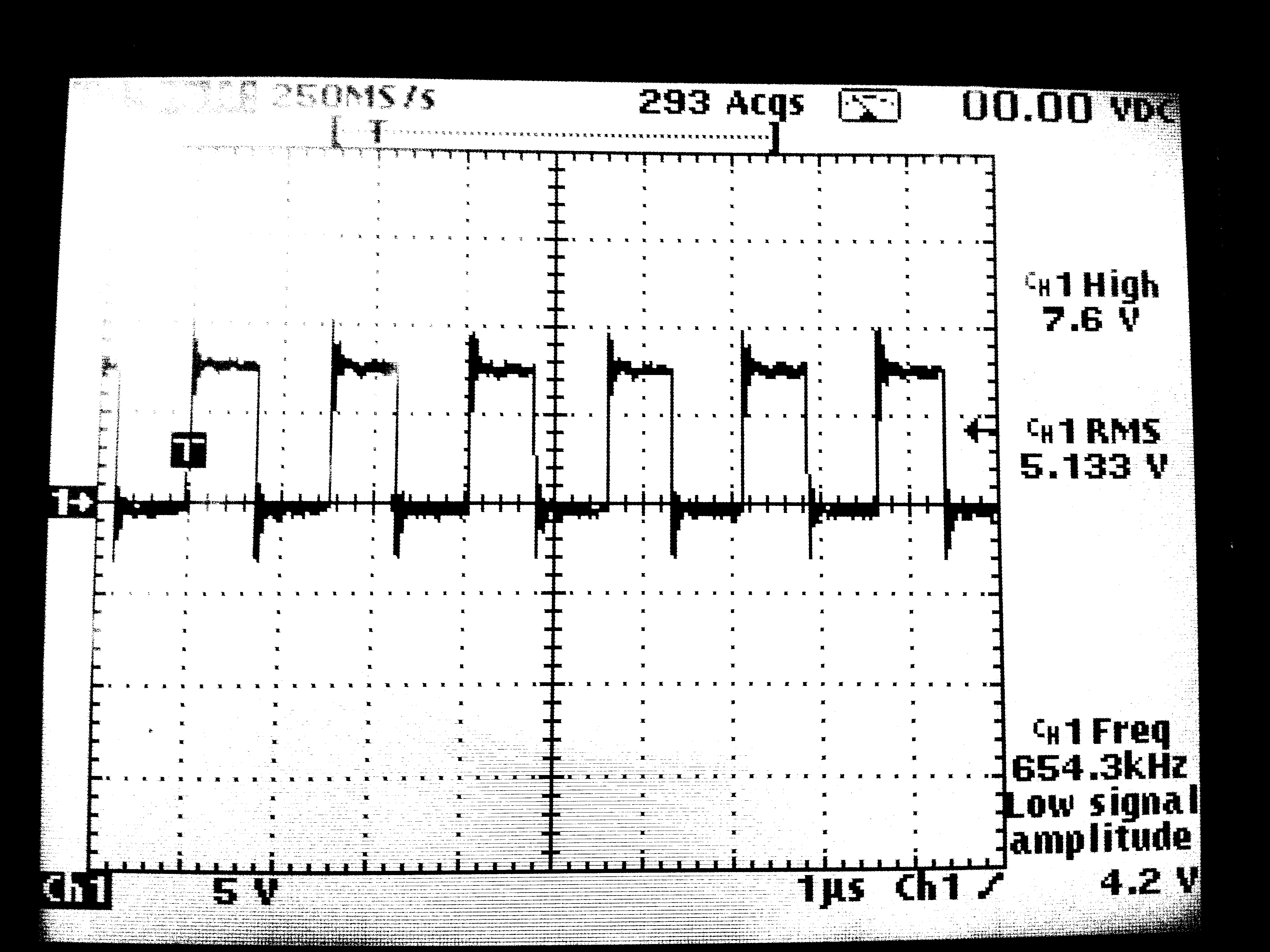
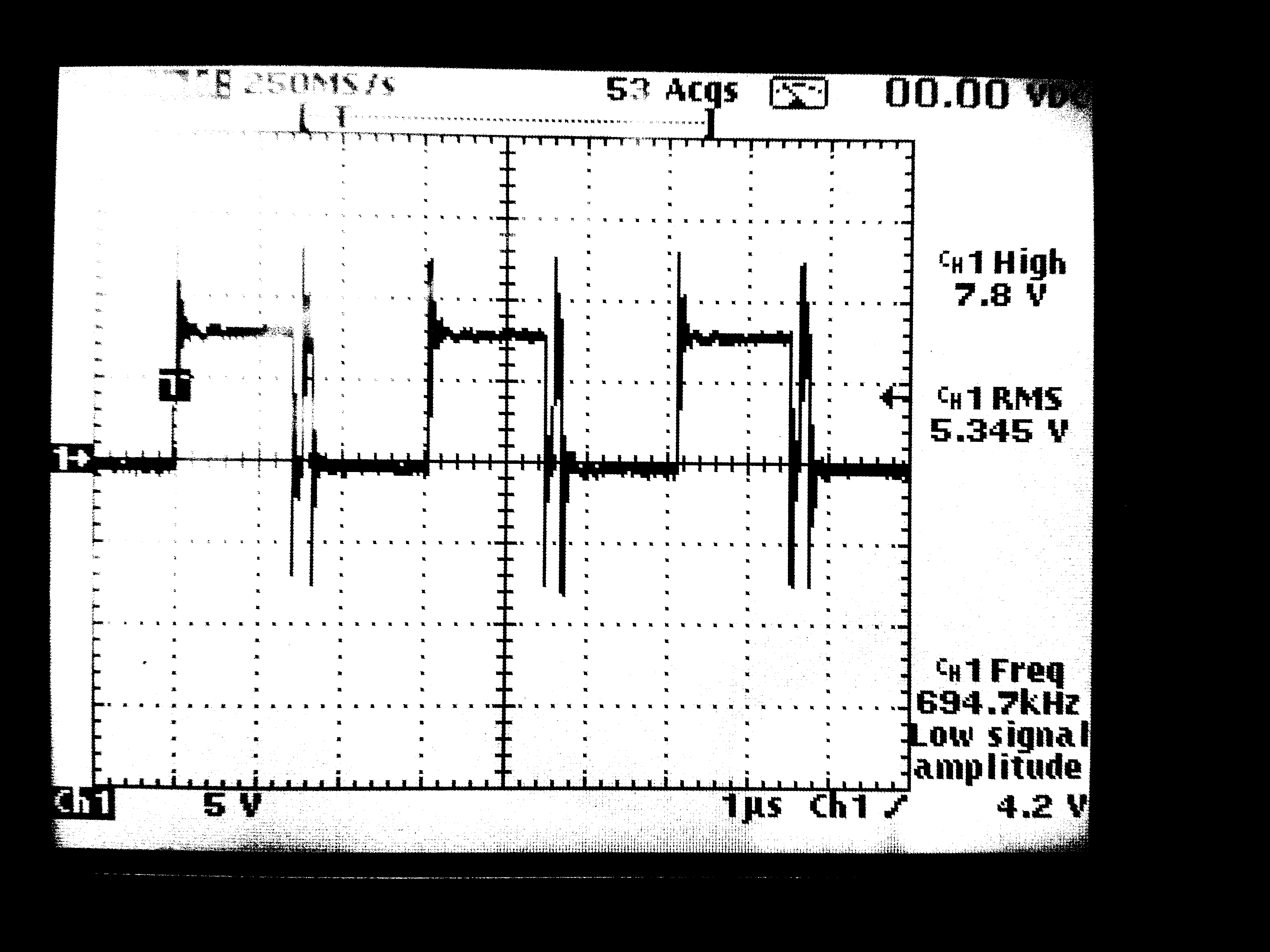
please, could someone help me with feedback compensation? What am I doing wrong, any RC value combination is not the right. Always some kind of feedback unstableness observed.

pwrd.pdf3323.LM5155_56_Excel_Quickstart_Calculator_for_Flyback_Regulator_Design.xlsx

Input 18-60V, output 24V, 5A. Transformer has 3:3:aux1 turns and 7uH primary inductance.

Thanks,

Jiri

  • Hello Jiri,

    Thank you for using our device. When reviewing your schematic and calculator, I cannot find anything major wrong. You are just using a very high output capacitance. 

    It would be very helpful to get some more insight in what you mean with feedback unstableness. Please share some measurements and possibly some information which RC combination you already checked and how these influenced the stability.

    I think that with the high output capacitance, it might be helpful to reduce the crossover frequency to the lowest value possible as there will be very slow voltage change on the capacitors which could cause the regulation to overshoot and undershoot before it observes the change. So increasing the capacitor and reducing the resistor would be my first recommendation until you get a stable output.

    In addition just for testing, I would remove the softstart transistor on COMP as this might have a negative effect. If this is the case, secondary side softstart might be the solution.

  • Hello Brigitte,

    sorry for delay, doing more things simultaneously.

    Desoldered C7 to lower output capacity. Secondary synchronous rectifier replaced by shotky diode. No compensation at all.

    Here are some oscilographs at switcher gate. What could be wrong, very unstable duty, at light load some pulse skipped, at hi load double pulses?

    I tried many RC combinations like 0R + 300n to 120k + 3n3. Am I right that RC should be at secondary and primary side? In calculator it's not clear, There are only Rcom and Ccomp, does it mean same values at both sides?

    Thanks

    Jiri

  • Another try:

    removed C22, so now is at output 4576uF. Compensation 22k + 100n at both sides. Removed R50 to disable freq dithering.

    At 0.5A load look ok:

    But at 3A:

    And occasionally load step 0 to 3A cause voltage drop near to 0.

    And what I forget, in all cases the ferrite produce huge noise - with freq dither: something like white noise, without: noise with dominant some audible freq..

    Jiri