This thread has been locked.

If you have a related question, please click the "Ask a related question" button in the top right corner. The newly created question will be automatically linked to this question.

TPS22941: Schematic for TPS22941

Part Number: TPS22941

Hi TI expert

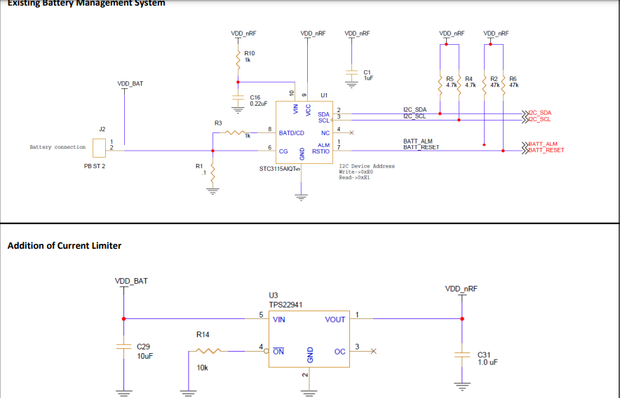
We have an existing PCB used for industrial IoT powered by 3.6V non-rechargeable battery. We intend to use TI current limiter IC TPS22941 for limiting current to 40mA and have revised our schematic. Appreciate if you could look at the attached schematic of TPS22941 integrated with our battery management system and advise if our understanding on the TPS22941 schematic is correct?

Best regards

Thomas

  • Hi Thomas,

    I cannot comment on how the device will interact with the battery monitoring system as I am not familiar with this device but what is your intention of using TPS22941 here? If the use case is to protect against overcurrent events larger than 40mA, then you can use TPS22941.

    TPS22941 is a power switch. It recognizes overcurrent event as faults, clamps the current to the value and then turns off the device. If the goal of the system is to hold the current at 40mA for long periods of time as a constant current regulator, then this will not work as the device has a thermal shutdown and auto restart feature.