This thread has been locked.
If you have a related question, please click the "Ask a related question" button in the top right corner. The newly created question will be automatically linked to this question.
Original Q:
Ernest,
It looks like you're hitting TON_MIN as mentioned in the previous post.
-Sam
Ernest,
You have rejected my "TI Thinks Resolved" but I don't see a message from you explaining what you'd like to further discuss.
For more context, see this video which explains the situation you're seeing.
-Sam
Why doesn't it work with no load or light load when this is the version I'm using:
8.4.5 Light Load Operation (FPWM Option)
For FPWM option, LMR23625-Q1 is locked in PWM mode at full load range. This operation is maintained, even
at no-load, by allowing the inductor current to reverse its normal direction. This mode trades off reduced light
load efficiency for low output voltage ripple, tight output voltage regulation, and constant switching frequency. In
this mode, a negative current limit of IL_NEG is imposed to prevent damage to the regulators low side FET. When
in FPWM mode the converter synchronizes to any valid clock signal on the EN/SYNC input.
I've used a smaller TI part with the FPWM Option in a different application it works as described.
The TPS560430XF maintains frequency down to zero volts output.
Sam,
I've used TPS560430XFDBVR in a different application and it stays at full frequency (1MHz) even with no load, and goes all the way down to zero volts driving a thermo-electric chiller.
8.4.5 Light-Load Operation (FPWM Version)
For FPWM version, TPS560430 is locked in PWM mode at full load range. This operation is maintained, even in
no-load condition, by allowing the inductor current to reverse its normal direction. This mode trades off reduced
light load efficiency for low output voltage ripple, tight output voltage regulation, and constant switching
frequency.
I understand min off-time and min off time but...
I thought that TON_MIN didn't apply to the LMR23625CFQDDARQ1 which I'm told is also FPWM.
My other application is running at 1MHz and has a 15uH inductor with a 15V input.
Here I'm running at 2MHz with a 10uH inductor with a 24V input.
Could I be running into IL_NEG Negative current limit (FPWM option) even with no load?
Thank you for your patience,
Ernest
Ernest,
The device cannot switch on for less time than TON_MIN. So your 43.7ns is being stretched to 60ns (typ). To maintain the correct duty cycle to maintain regulation, TOFF is also being extended by that same percentage (60/43.7).
To maintain a fixed frequency you will need to reduce the switching frequency, reduce VIN, or increase VOUT.
-Sam
Sam,
You seem to be describing the PFM option not the FPWM option which is supposedly what DigiKey delivered to me.
This part does not work as described with no load (except for the feedback network), 392 ohm load, 100 ohm load or intended 15 ohm load.
I previously used the FPWM option TPS560430 for another application and it worked perfectly with no load as well as light load down to zero V with no frequency deviation,
The description of the LMR23625-Q1 is almost identical.
My understanding is that the low side FET stays on for an extended time and discharges the output capacitors to compensate for the excess TON_MIN.
If I actually have the FPWM version (which is in question in my mind), why doesn't it work at no load?
The only difference in the description is the mention of "IL_NEG":
"In this mode, a negative current limit of IL_NEG is imposed to prevent damage to the regulators low side FET"
Question: How does the "negative current limit" work? Does FPWM revert to PFM under this condition?
If this is what is happening, what can I do without changing my 24V supply or my minimum variable output of zero V.
-Ernest
LMR23625-Q1 SIMPLE SWITCHER® 36-V, 2.5-A Synchronous Step-Down Converter
The device has option for fixed-frequency, forced pulse-width-modulation (FPWM) mode to achieve
small output voltage ripple at light load.
8.4.5 Light Load Operation (FPWM Option)
For FPWM option, LMR23625-Q1 is locked in PWM mode at full load range. This operation is maintained, even
at no-load, by allowing the inductor current to reverse its normal direction. This mode trades off reduced light
load efficiency for low output voltage ripple, tight output voltage regulation, and constant switching frequency. In
this mode, a negative current limit of IL_NEG is imposed to prevent damage to the regulators low side FET. When
in FPWM mode the converter synchronizes to any valid clock signal on the EN/SYNC input.
TPS560430 SIMPLE SWITCHER® 4-V to 36-V, 600-mA Synchronous Step-Down Converter
The TPS560430 also has FPWM (forced PWM) version to achieve constant frequency and small output voltage ripple over the full load range.
8.4.5 Light-Load Operation (FPWM Version)
For FPWM version, TPS560430 is locked in PWM mode at full load range. This operation is maintained, even in
no-load condition, by allowing the inductor current to reverse its normal direction. This mode trades off reduced
light load efficiency for low output voltage ripple, tight output voltage regulation, and constant switching
frequency.
Ernest,
I don't mean to frustrate you or ignore your questions. The fact is that the device needs to switch on for at least TON_MIN to provide enough time for the leading-edge blanking of the current-sense. This is true for every current-mode buck regulator. The reason you did not see this reduced frequency in other designs is probably because you were not hitting TON_MIN.
FPWM is a mode that forces the device to switch to keep continuous conduction (inductor current always ramping up or down, never staying at 0). AUTO/PFM/DEM mode will set SW to high-impedance when the inductor current ramps to 0A but FPWM will keep the low-side FET on causing the inductor current to go negative. This does not mean the device will ignore TON_MIN. The device can never switch for less time than TON_MIN in normal operating conditions.
IL_NEG (negative current limit as you've mentioned) is about -2A (typ). You can use equation 11 in the datasheet to calculate the inductor ripple. If ∆IL/2 > 2A, you will hit IL_NEG at no-load FPWM operation. The end of section 8.3.9 states:
"For FPWM option, the inductor current is allowed to go negative. If this current exceeds IL_NEG, the LS switch is turned off until the next clock cycle. This is used to protect the LS switch from excessive negative current."
Please let me know if I've missed something or if something is unclear.
Thanks,
-Sam
I found the answer to one of my questions under: 8.3.9 Overcurrent and Short-Circuit Protection
For FPWM option, the inductor current is allowed to go negative. If this current exceeds IL_NEG, the LS switch is
turned off until the next clock cycle. This is used to protect the LS switch from excessive negative current.
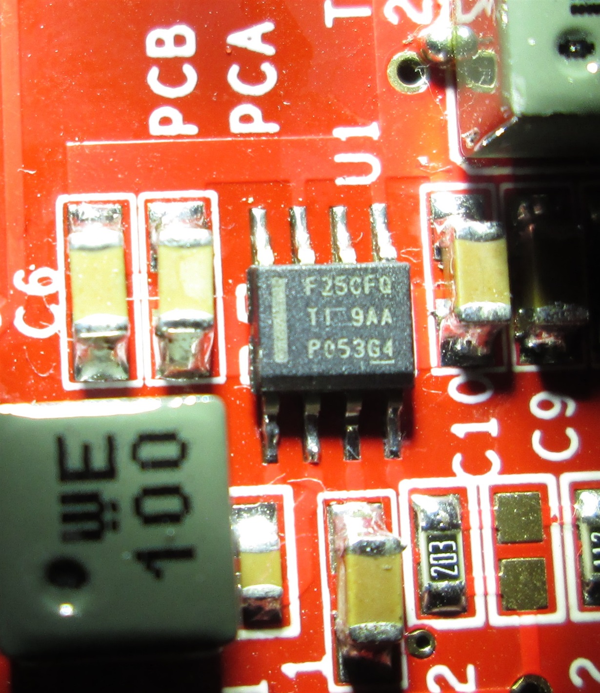
Attached are pictures of the IC and the DigiKey packaging which I doubt is actually the FPWM version.
Ernest,
The label on the bag and the top marking align with this IC being FPWM.
Please let me know what additional questions you have.
-Sam
Sam,
I did some simple simulations which verified your central point about duty cycle and called into question my understanding of how and why my previous FPWM application worked so well.
In that TE driver application it worked over a wide range but was never tested quite all the way to zero output.
Maybe peltier's the back-EMF characteristics helped somehow.
The only way I could imagine running into the low side FET current limit at low output voltage was the output capacitance being too big.
Sure enough, in my simple simulation with 40uF it was going way over the limit. Reducing the output capacitance to 10uF kept it below IL_NEG.
Next I'll reduce the capacitance on the board and see what it does in the real world.
Thanks,
Ernest
Hello Sam,
I collected some scope traces at low output voltages and I was able to see some instances of ringing which I guess was from the low-side FET turned off due to overcurrent.
I took out three of the four 10uF output caps and that was the end of the ringing, but course the ripple went up.
I understand most of what I'm seeing now and I'm clear on why I can't get gracefully to zero volts output.
What has been confusing is that I have captured frequency variations but these happen around the stop and restart of switching which I guess is due to output overvoltage.
In reality, this application doesn't need to go to to zero V output.
I could disable it below 3V output and the system functionality would be practically identical.
I've ordered some of the PFM version to compare theiir operation in this prototype design.
Thank you for your patience in bringing to light my misunderstanding of the limits of FPWM.
Best regards,
Ernest