Other Parts Discussed in Thread: TPS1H000-Q1
in an actual application this device is used to drive a DC contactor (Gigavac HX241) with 24V coil (dual coil design with economizer, the first bigger coil is internally disconnected after pick-up).
This contactor has an integrated coil suppression. External coil suppression is not recommended and is not implemented, because this would slow the release time wich could reduce life cycles and lead to contact welding.
- The contactor's back EMV is 55V according datasheet for the 24V coil version.
- The TPS1H100-Q1 has a drain-source clamp of appr. VDS,clamp=58V at room temperature according Fig. 14 in datasheet.
Actual measurement with Vin=24V shows on Ch3 the coil voltage referred to GND when switching the coil off.
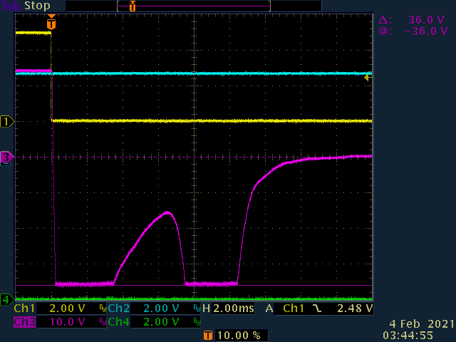
So the voltage across Drain-Source of TPS1H100-Q1 is 36V + 24V = 60V (@ 25°C).
The waveform shows that the voltage is clamped by the TPS1H100-Q1, right?
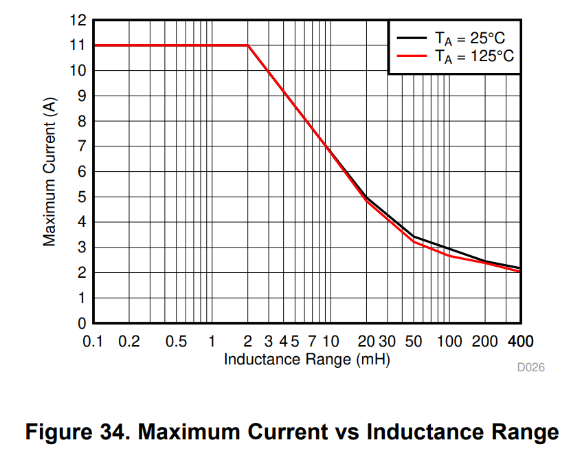
How can I estimate if the IC can handle the switch-off energy, or if it needs external drain-source protection?
Unfortunately, there is no information about the coil's inductance(s).
However, the hold current after pick-up ist 90mA @ 24V continuous.
Regards, Oliver