This thread has been locked.

If you have a related question, please click the "Ask a related question" button in the top right corner. The newly created question will be automatically linked to this question.

LM25085: Did LM25085 used in Constant current output mode?

Part Number: LM25085
Other Parts Discussed in Thread: LMR14030, TPS92692, LM61440, LM25145

Currently I want to design a BUCK circuit, 24V input and 1~20V output, 3A constant current output.

I find the LM25085 IC, but from the datasheet it's D-CAP mode and used generally in constant voltage mode..

Can it be used in constant current mode? If yes, how I design the feedback circuit?

  • Hi Fleming,

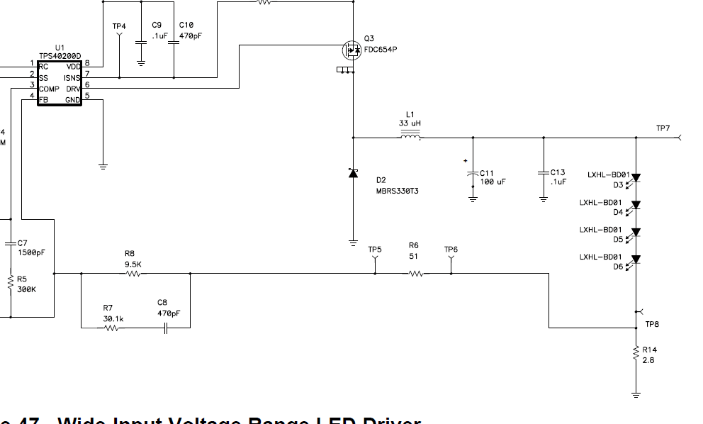
      If a CC regulator is needed,you can add a CS resistant between Load and GND to detect the load current. FB shall  be connected to the top of CS resistant. I found a similar application for you. Please refer to LM40200 datasheet section 8.2.3. The principle is the same. It will be better if you can simulate the loop stability to verify your design.

      If you want a CC/CV regulator, please refer to this application note: Constant Current Constant Voltage Buck Converter w/LM25085.

      Please feel free to get in touch with us if you had more questions.

    BR,

    Victor

  • Dear Victor,

    Thanks very much for your support.

    It's very useful for my design. For cost reason, it seems that LM25084 is competitive. If I only want CC mode, how can I modify the circuit in the applicatio note?

    No need for FB circuit? Or just disable the FB circuit? And for the decriptio, in CC mode, it seems that it's peak current control, then if the duty cycle is larger than 0.5, slope compensatio needed?Then how can I add the slope compensatio?

    For LM40200, the gate driver is only 200mA, if the output current is as high as 5A, is it enough? How can I boost the driver capacity? For example, push-pull?

    Thanks for your information.

  • Dear,

    Can you give me some information?

    Thanks

  • Hi Fleming,

      My apologize for the delay.

      If you only need CC, the circuit in application note is not suitable for you. You can use LM25085 with current sense resistant and delete Rfb1 and Rfb2. I mentioned LM40200 just because we can learn  how we achieve CC from it, which can be used in LM25085 CC design.  Like the picture below, R14 is current sense RES. R6 is pre-reserved for Loop Stability test(injection res). R7,R8,C8 is designed for compensate. This may also be used in LM25085.

      Rsense=Vfb/Iout=1.25V/3A   Rinj=50Ω

    BR,

    Victor

  • Hi Felming,

      What's the load you use? Do you have LM25085EVM or test bench on hand?

    BR,

    Victor


  • Dear Mr.Yu

    I think for the LM25085 and LM40200, they're different. In LM40200, there's comp pin out, and in the circuit in datasheet, C7/R7/R8 are loop compensate circuit.  But for LM25085,there's no comp pin,R7/R8/C8 is not between FB and comp. Then how can we get the constat current mode?

  • My load is battery and I have no EVM on hand, currently I analyze the IC to desig the concept.

  • Hi Fleming,

      The compensate is OK, R7/R8/C8 is between Rcs and FB pin , but there are still some points need to check with you.

      1. Can the GND of battery pack floating? If not, we need a high side current detect(like the app notes did).  Does the battery need a  CV charge mode?

      2. LM25085 FB is 1.25V, as load current is 3A.It will bring 3.75W power loss on current sense RES.  An amplifier will be needed if you want to use a smaller RES,which will increase the COST.

          Constant-on-time mode device is not very suitable to realize a CC mode buck, which may have some difficulty in loop stability. 

      3. I think LMR14030 should be a better choice than LM25085. LM14030 is peak current control mode and has 0.75 FB ref. 

      5. TI  LED drivers contain a lot of CC mode buck, you can also consider TI LED driver products.

  • Thanks for your suggestion.

    In my design, no need for CV mode and also the battery GND can be float.

    TI LED driver used for CC mode buck, it's a good direction. Can you suggest a chip?

  • Furthermore, I prefer to use the external MOSFET for the thermal reason. Can you suggest a chip?

  • Dear Victor

    Can you recommend an  chip for the BUCK CC mode?

  • Hi Fleming    

       For LED driver, you can consider TPS92692.

    Victor

  • Hi Fleming,

      If you can accept BUCK converter, LMR14030 or LM61440/60 are all not bad.  But thermal will definitely be a big challenge at 20V/3A

      If you need buck controller, you can consider LM25145. I also found a related design for you. Please see the file below. This design can reduce the power loss on current sense RES without using an amplifier.

    CC mode buck design.pdf