This thread has been locked.

If you have a related question, please click the "Ask a related question" button in the top right corner. The newly created question will be automatically linked to this question.

BQ27621-G1: I2C NACK on power-up

Part Number: BQ27621-G1
Other Parts Discussed in Thread: EV2400

I am working on a bug for a customer where certain units fail to communicate via I2C with the BQ27621-G1 fuel gauge.  The host processor is an STM32F4 part (sorry, TI ).  Here is our circuit design:

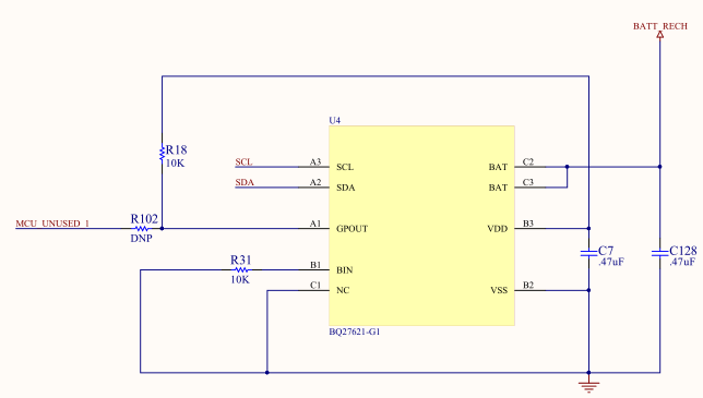
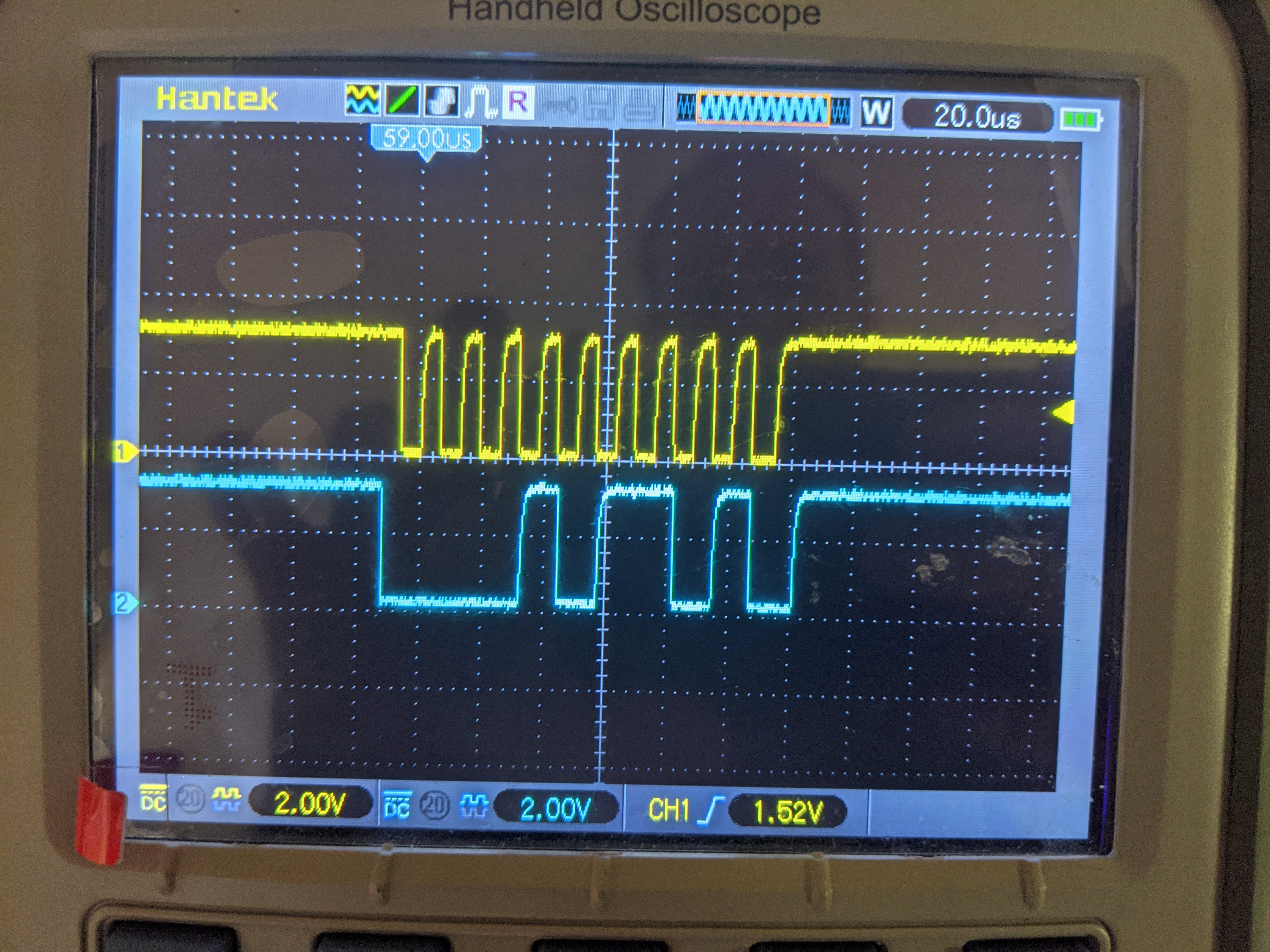
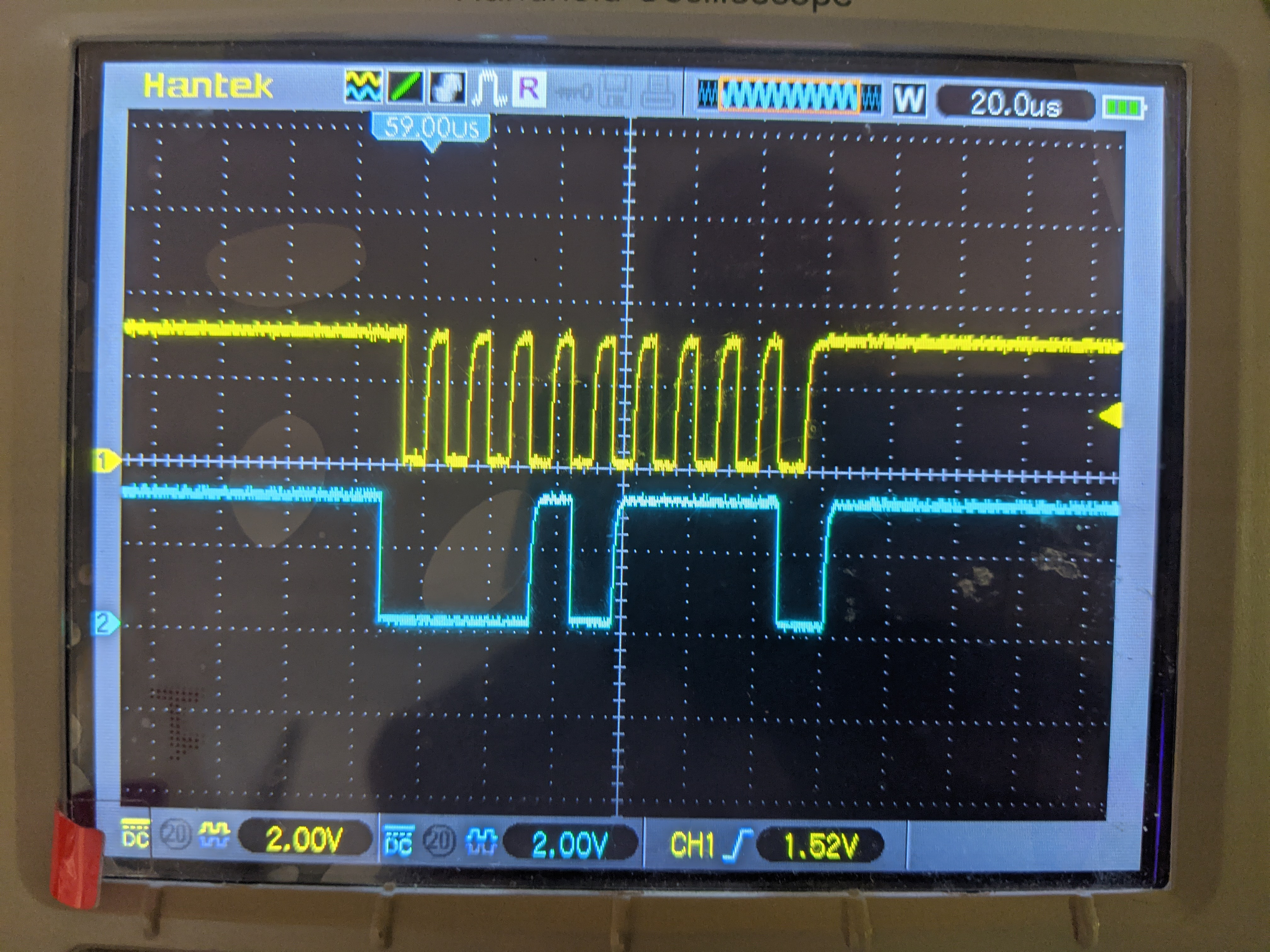
It has been quite difficult to characterize this mode.  The few times I have been able to duplicate it in a controlled way is by disconnecting the battery, waiting until any voltage in the circuit dissipates (particularly across VBAT), then reconnecting the battery.  Once the part is in this state, it NACKs any I2C communication until a power cycle, like so:

I measured what I could around the circuit while the chip is in this state:

  • VDD = 1.81V
  • VBAT = 3.93V
  • GPOUT = 1.79V
  • BIN = 0.00V
  • SCL & SDA idle = 3.01V (pulled up to 3.3V elsewhere in our schematic)
  • The I2C peripheral is operating properly, as communication with other slaves continues.

Things I have tried to get out of this mode:

  • Slow down I2C clock from 100khz down to 10khz
  • Toggle GPOUT low & release (manually with a probe)
  • Toggle BIN low & release (manually with a probe)
  • Hold both SDA and SCL lines LOW for 2 sec (in firmware)
  • Send a RESET Control() command

I have seen several other forum posts with this issue, but they either have suggested what I have already tried above, or there was no resolution.  Please help!

  • Hi Elliot,

    You may want to check if clock stretching is supported on your host processor. Does this issue also happen with ev2400?

    Best regards,

  • It is definitely supported.  I have seen long stretches on the o-scope where SCL is held low in the middle of a byte (before ACK).  Particularly when doing the address setup for a block read/write.

    I do not have the ev2400 kit.

  • Hi Elliot,

    The gauge could be entering a “fail-safe” mode during boot up. Does the gauge responds on (8-bit extended) 0x16 instead of 0xAA? Read one byte from register 0x00, I2C address 0x16. If it ACKs then the gauge entered ROM mode.


    You might also try removing the pull-up from GPOUT to VDD (it should be pulled up to your IO rail (e.g. the I2C rail), not VDD. 

    Best regards,

  • Nick,

    I tried sending 0x16 and still get a NACK.  I assumed this was already shifted.  I attempted both a read and a write of 0x16.  Scope traces:

    Prior to posting, I used GND, 1.8V and the 3.3.V supply (same supply as I2C line supply) to toggle GPOUT in an attempt to 'wake-up' the chip.  None of these resulted in clearing the I2C communication.

    One thing I've been wondering about - at the end of the I2C transaction, it appears there is a LOW toggle of the SDA line.  Is this some sort of delayed ACK from the chip?  Nevermind - I realize now this is just the stop bit.

    Thanks,
    Elliott

  • Hi Elliot,

    We are looking into this further, you can expect a reply back by friday.

    Best regards,

  • Elliott,

    The 8101 needs at least 2uF cap to startup reliably. Make sure that the derated value of your cap over voltage and temperature is still at least 2.2uF. TI recommends using a 4.7uF to account for derating.

    Thanks,

    Eric Vos

  •  - Thanks for the reply.

    I'm not sure what the 8101 refers to I suspect the 8101 is the internal LDO.  I assume you are talking about the capacitance on the BAT input pin (across the LiOn battery terminals).  Elsewhere in the circuit, we have a 1 uF capacitor, which gets closer to the 2 uF you recommend.  However, this is some distance away from the fuel gauge.

    I will look into replacing our C128 (the cap right next to the fuel gauge) with a 4.7 uF capacitor and see if that helps.

    Why is this information not in the datasheet?  The datasheet only calls for a 1.0 uF capacitor on the BAT line.  Also, the recommended operating conditions show a nominal 0.1 uF capacitor:

  • Looking more into the 8101 LDO - are you recommending to put a 4.7 uF capacitor on the LDO output?  That's what the datasheet for the 8101 recommends for stability.  This may make some good sense, since we are not using the 1.8V output for anything at all - it's only loaded by the output capacitor.

  • Elliott,

    Sorry for my delayed response. You are correct we are recommending a 4.7uF cap on the LDO output to help stabilize the "Hot-Plug" type of test. Was this able to resolve your issue? 

    Thanks,

    Eric Vos

  • Eric,

    Preliminary testing shows that this does indeed solve our issue.  I trust that on your end the datasheet & reference manual documentation will be updated accordingly.

    Thank you for the review & response,
    Elliott