This thread has been locked.

If you have a related question, please click the "Ask a related question" button in the top right corner. The newly created question will be automatically linked to this question.

UCC27712: Bootstrap gate driver

Part Number: UCC27712
Other Parts Discussed in Thread: SN6501

Hi ,

I have selected UCC27712 for my application requirement of driving a BLDC motor.I need to apply gate pulses of format as shown in below figure to my device.

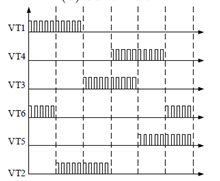
Here VT1 is my high side pulse and VT4 is my low side pulse of single half bridge.Switching frequency is 100kHz. My design stage is almost ready,but now I am encountering certain doubts.

1)For bootstrap capacitor to charge,low side device has to be turned on .Here as you can see my low side device ie. T4 gets turned on only after some duration. i.e complementary switching is not iplemented here.

So,will this circuit operate properly.Will the bootstrap capacitor hold charge for that large time and provide gate requirements to my high side device.

2)

If I needed to apply this gate pulse pattern,is it possible for my bootstrap capacitor to provide 100% duty or do I need some additional charge pump circuitry.

Regards,

Reshma

  • Hello Reshma,

    For bootstrap capacitor design guidelines, refer to section 8.2 of the UCC27712 datasheet. There is guidance on how to determine the boot cap value based on application parameters.

    In your case, the switching frequency regarding the boot cap value, will be based on the "burst" frequency since there will be long times that the low side is not switching to recharge the boot capacitor. Determine the longest off time that the low side FET is not switching and repetition rate of the burst waveform. Depending on how long the low side is not switching will determine if you can have a reasonable value bootstrap capacitor or may need a dedicated floating high side bias, which can enable very low frequency and DC operation of the high side gate driver.

    TI does sell devices targeted for the high side floating bias, the SN6501 and SN6505 are small simple devices that can generate the high side bias.

    Is there a maximum time that the low side FET will not be switching, and a minimum repetition rate of the PWM-pulse train?

    Confirm if this addresses your questions, or you can post additional questions on this thread.