Hello TI Team,
while testing a BMS for a 7S battery, we have a question about the result of our short circuit test.
Set-up description:
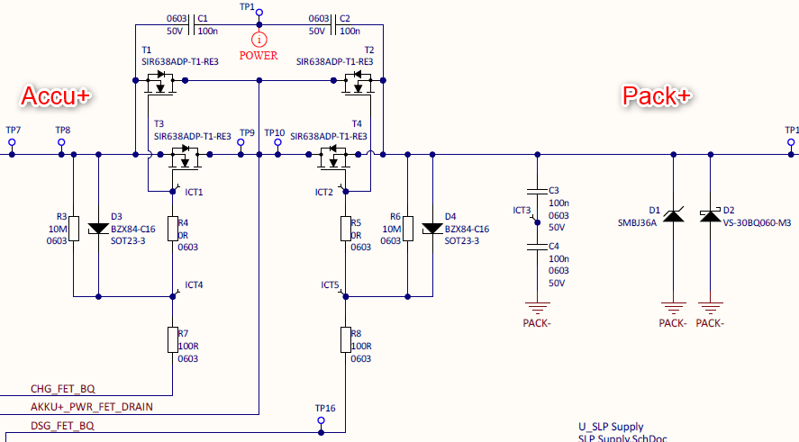
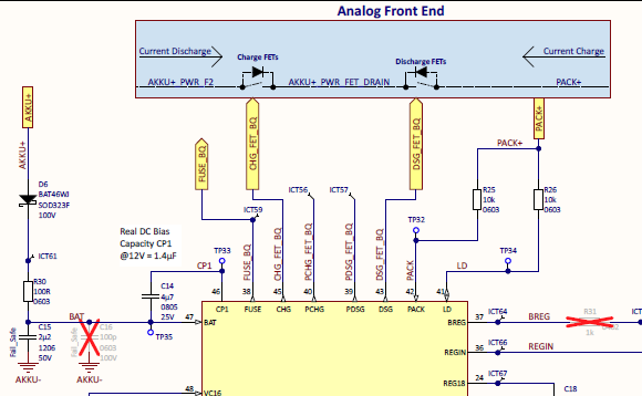
On the BMS we use two CHG and DSG FETs each in series mode (high side).
On the low side we use a 0.5mOhm shunt.
To measure the short-circuit current, we have connected another 100µOhm shunt externally to PACK-.
BQ Setting:
SCD threshold = 2 (40mV)
SCD Delay = 15µs
SCD Recover = 30s
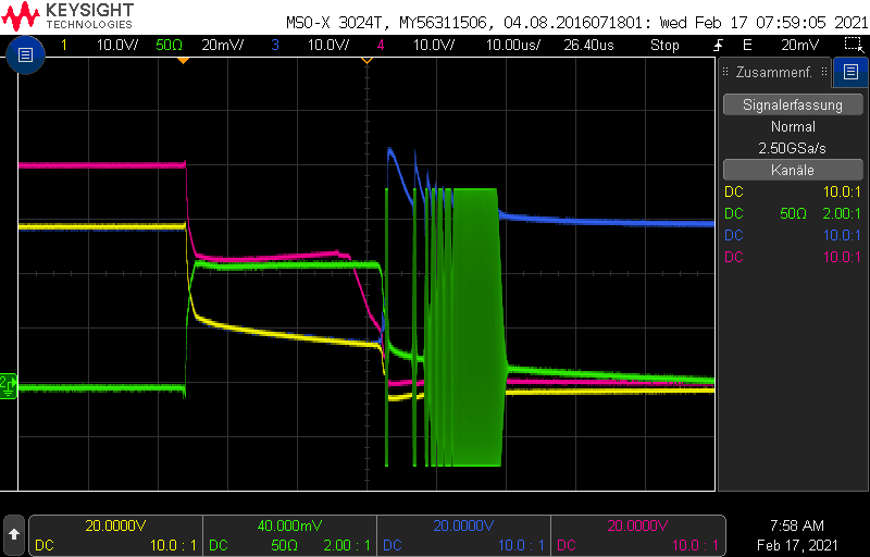
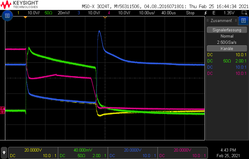
The following image was captured with the oscilloscope:
Ch1 (yellow) = PACK+
Ch2 (green) = Voltage over 100µOhm Shunt (Short-Circuit current)
Ch3 (blue) = Drain Voltage of DSG FET
Ch4 (red) = Gate Voltage of DSG FET
After the drain voltage goes high when the FETs are switched off, the FETs seem to switch on and off for a short time.
Can you please help me?