This thread has been locked.

If you have a related question, please click the "Ask a related question" button in the top right corner. The newly created question will be automatically linked to this question.

UCC28634: Very Low output Current

Part Number: UCC28634

Hello All,
I am using UCC28634 for 150V-265VAC to 5.00VDC @ 6A 
The circuit and transformer specs are as per TI webench reports
The circuit output is 5V at no load Connected 
as soon as I connect a resistive load for example a 10-ohm resistor ()
the output voltage drops to zero 
and I can hear an audible noise in form of ticking across the transformer
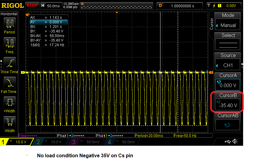
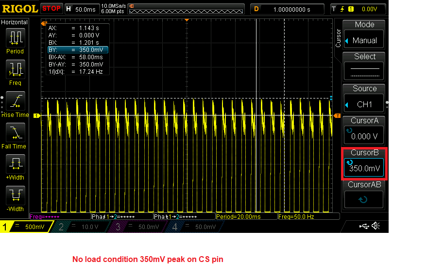
attaching images of output voltage in both the conditions
I think the controller does not change the PWM frequency for MOSFET even if there are changes in  output current
I am also attaching the circuit Diagram and transformer report


 CoreCoilformer23.pdf
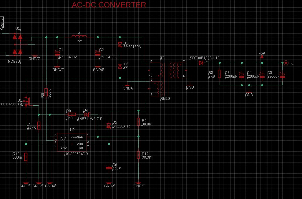
  • Hi Rushab,

    in you schematic, there is a mistake on aux-winding of the transformer The homonymous ends should be at Ground point.

    please double confirm whether it is the root cause.

  • Hello David
    Thank you for you're response
    The schematic symbol for aux winding is wrong 
    I cross-checked it with the original transformer
    the homonymous ends are connected to ground 

  • Hi Rushab,

    if the transformer homonymous can match the PCB layout, please double confim the CS signal waveform to see whether an over current protection is triggered.

  • Hello David 

    Yes the Over Current is triggered
    in the no-Load condition, the voltage at CS pin (with respect to GND of the chip) is around 350mV
    as soon I Connect the Load the voltage Jumps to 3V 
    also, there is a -35V on the CS pin, irrespective of the load is it normal?
    Sharing all the Images from the scope


  • Hi Rushab,

    Thanks for your interesting in TI's part.

    Here are some comments for your reference:

    1. The maximum allowed voltage for CS pin is -0.3V~1.5V . so if you captured  a -35V and +3V voltage on CS pin . The controller already damaged . or you didn't captured a right signal. CS pin waveform should likes a triangle shape with some spikes.

    2. Auxiliary winding "dot-end" should be connected to rectifier diode rather than ground.

    3. The SD pin can connect a 200kohm resistor if you don't want to use it.

    4. You can capture MOSFET VDS , transformer primary winding current . VDD in the same waveform for analysis . all of protection are listed in datasheet page 43 table3 . You can check it one by one.

    Thanks.

  • Hello,
    Thanks for your reply
    yes, the chip indeed was damaged
    the problem still persists even after changing the chip
    I thought it might be because of poor layout or noise 
    so I removed the MOSFET and Mounted it on a secondary board and Connection is done Via Wires
    I Have Added a 1nF and 1k Resistor on the cs pin as a filter yet no effect
    by Observing the waveform on the secondary of the transformer, I can see the MOSFET turns on every 500mS and turns back off
    so it is not able to deliver the current needed

  • Hi Rushab,

    Could you please share some waveforms which you captured and some photos show how you to do the test ?

    And can you capture the signals which I mentioned in last reply ?

    Thanks.

  • Hi Jaden
    I will share the waveform as soon as I have them

    in the above you mentioned point 3

    3. The SD pin can connect a 200kohm resistor if you don't want to use it.

    can you clarify that the 200k resistor should be Pulled up, Pulled down or Floating

    Thanks in advance

  • Hi, RUSHAB,

    Sorry for confusing you. the resistor on SD pin should be connected to ground.

    Thanks.

  • Hi Jaden
    Thanks for your response I Connected a 200K resistor between SD and ground but it had no effect on the output current

    I don't have any Isolation probe to Capture the VDS of MOSFET sorry about that 


    However, I Disconnected the aux winding in the circuit and Captured the waveform
    the following image is of the first 3 Pulses that the controller generates after every reset
    What I Found was the waveform when MOSFET is ON is does not reach the value VIN x (NB/NP) = 345VDC x (8/50)=55.3
    it is 40V in my observations also it is not flat either 
    As mentioned in Figure 23 page 24 of Datasheet

    Also notice a Spike on the Positive side of Waveform not sure the cause for it 

    I guess the issue could be Improper Mosfet or the transformer core Saturation 
    Attaching the Datasheet for MOSET here https://www.onsemi.com/pdf/datasheet/fcd4n60-d.pdf

    Thanks 


  • Hi RUSHAB,

    Firstly , make sure your transformer windings' polarity are correct , otherwise , there is a short through happens when mosfet turn on leading to a very narrow pulse . the waveform shows the first pulse not turn on . and 2nd and 3rd are very narrow .

    Secondly , please add a RC filter on CS pin , just shown in EVM board design(R=1K .C=120pF) to filter the leading edge blanking spike . so you will not see a very narrow pulse .

    UCC28634 driver capability is enough to turn on the mosfet you selected .