This thread has been locked.

If you have a related question, please click the "Ask a related question" button in the top right corner. The newly created question will be automatically linked to this question.

UC1825: Are there any failures that can cause PWM to continue when SS is active?

Part Number: UC1825

Hello,

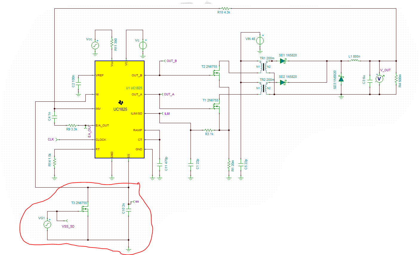
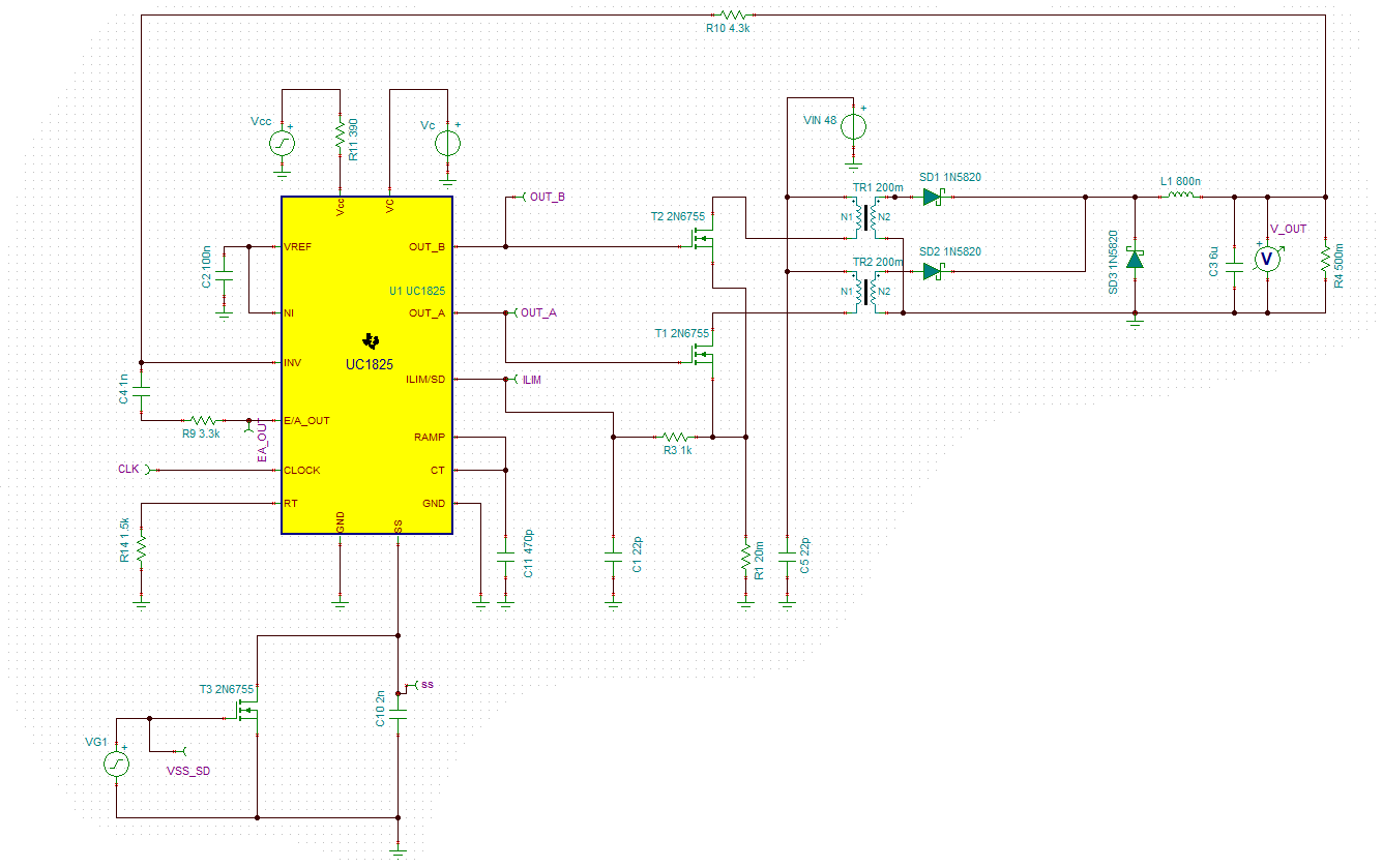
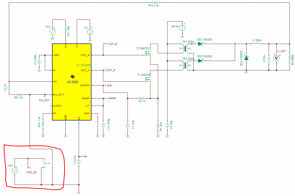
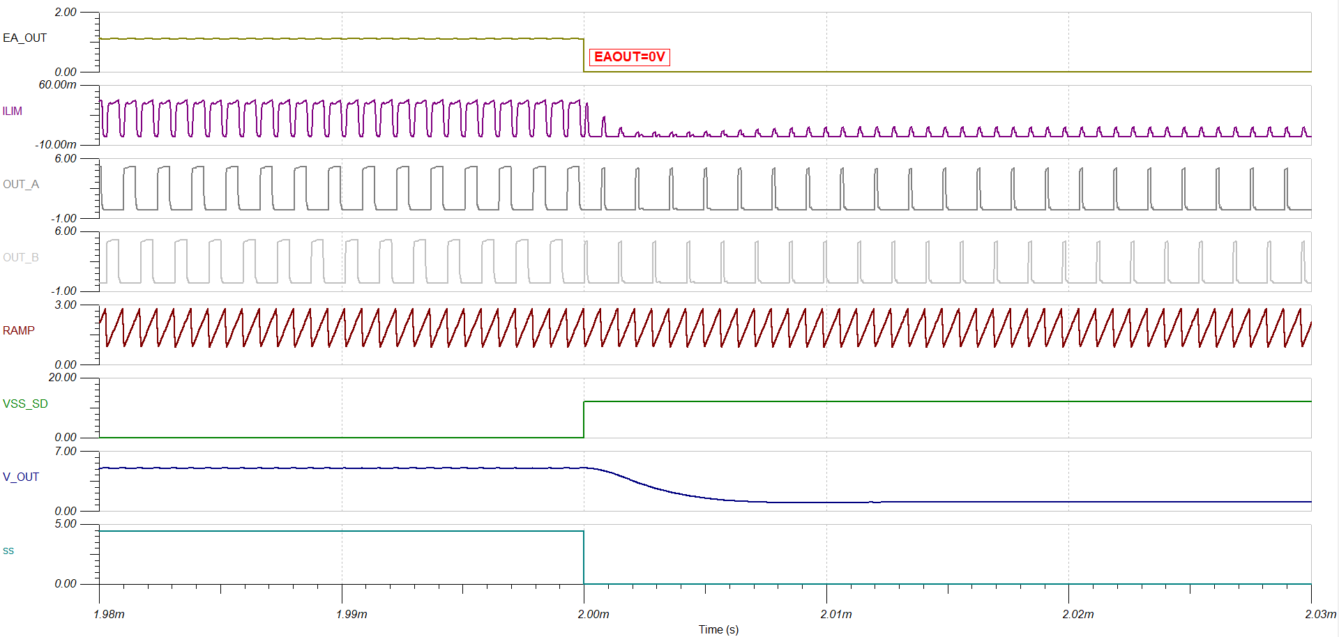
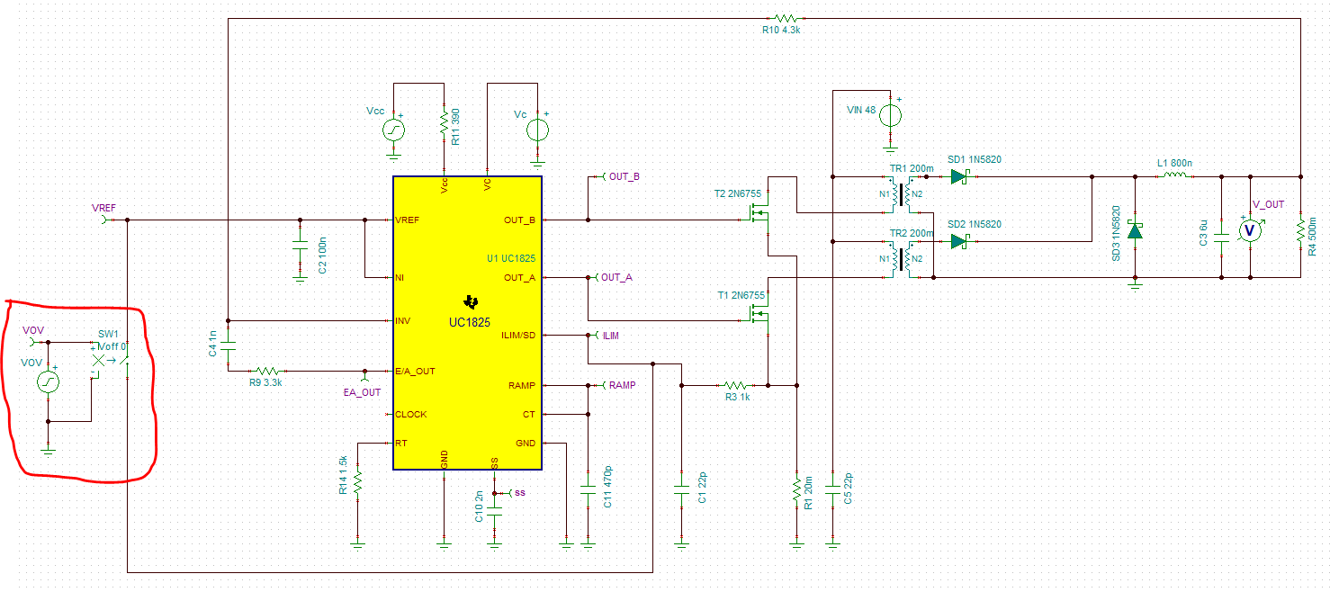
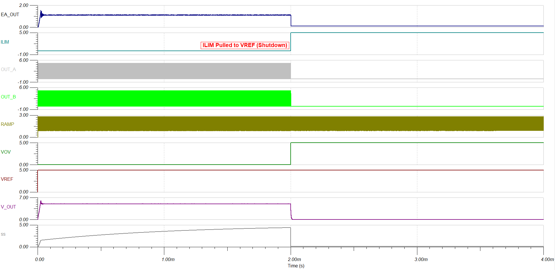
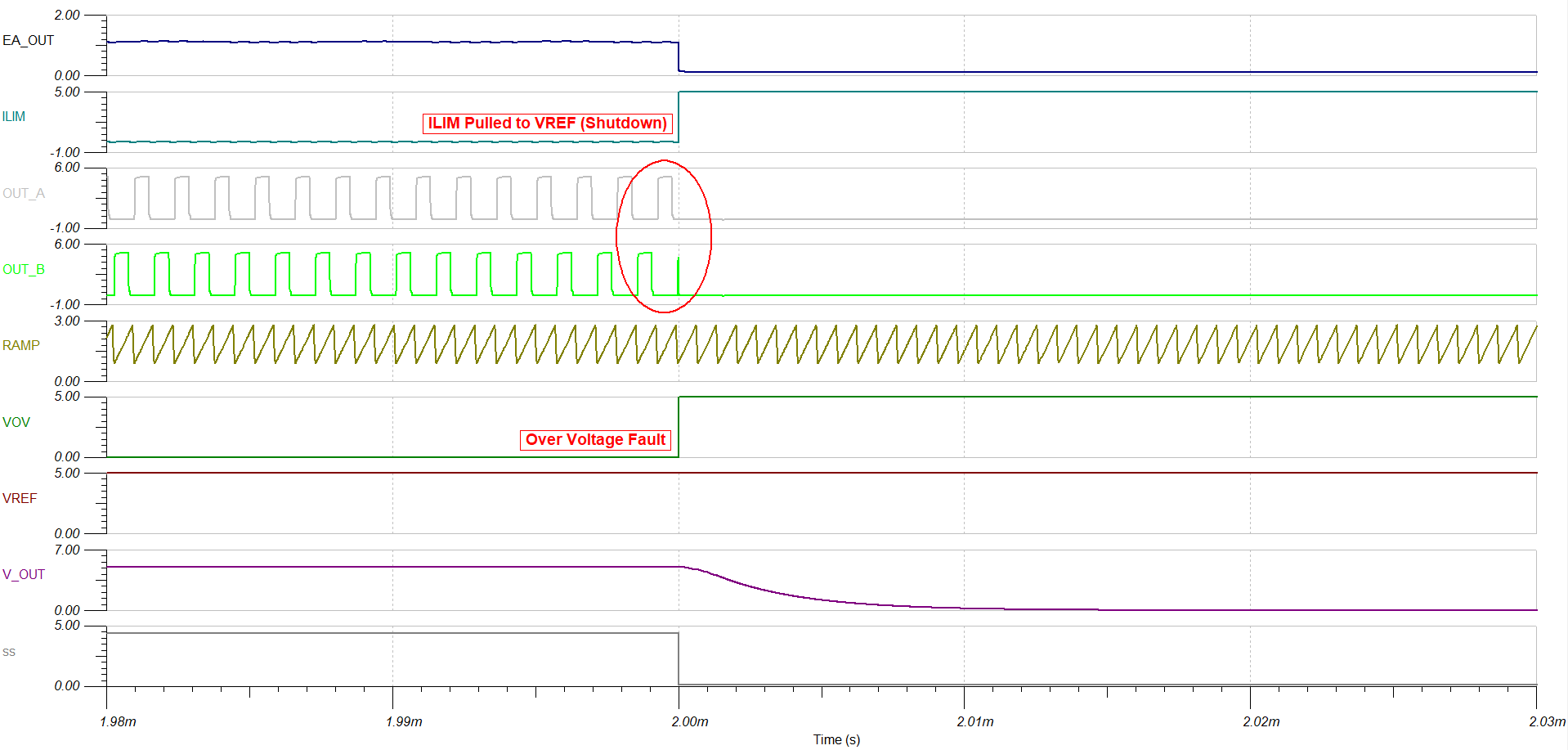
I am trying to find out if there is any testing or failures of this device that would somehow cause the PWM outputs to remain active while soft start is pulled low. A customer is using SS tied to the NINV pin as an overvoltage monitor in conjunction with the affected power supply connected to INV. The only conclusion I can come to is that this is only possible if there is a failure inside the unit that internally stops the S/R flip flop from Setting. Are there any known failures of this device, or any testing to show that this is not possible without the device becoming inoperable? 

Thanks

  • Hi Brody,

    Under whatever OVP conditions that result in pulling down on soft-start, can you isolate the SS pin and try pulling SS to GND on it's own and then try pulling NINV to GND with SS already pulled to GND? When SS is pulled to GND, all OUT switching is disabled. Can you provide a schematic of how the described connections are made?

    Steve M

  • Hi Steven,

    Unfortunately I cannot test this in a lab environment currently. And all schematics are proprietary to the vendor. The connects are that NINV is connected directly to SS. SS is connected to overvoltage monitoring circuitry that normally provide a ~15V signal to SS, but goes low when an OV condition occurs which would stop all switching. I am trying to understand if there is a way that the IC can fail, or has failed in the past, that allows for SS to not function properly, while also allowing the chip to operate when NINV is lower than INV. In this case, INV would be the monitored power supply voltage, but in my failure scenario, it fails to ~30V. 

  • Brody,

    There is an internal 9uA constant current source pushing current out of the SS pin. The expectation is that the load on the SS pin is a fixed capacitor that gets charged up to VREF (5V). With SS connected to NI, you are relying on a current into a capacitor as the reference into the error amp (NI). When the OV occurs, NI/SS are pulled LOW and INV is heading LOW as VOUT capacitors are discharging. It could be that the timing of NI vs INV both going LOW is an issue? Then there is the scenario that perhaps the output capacitors have no fully discharged but the OV condition is removed and the restart happens into a prebiased load. 

    I added this pulldown to the TINA sim you can download from the UC1825 product folder. I allowed the sim to run for 4ms and then apply the gate signal at 2ms to simulate the OV fault:

    At 2 ms, SS gets pulled LOW, but OUT_A/OUT_B remain switching, which keeps VOUT>0V and therefore keeps INV>0V

    Disconnect SS from NI and connect NI to VREF:

    Similar to previous sim, at 2 ms, SS gets pulled LOW but OUT_A/OUT_B remain switching, same result so it seems this behavior is independent of whether SS or VREF serves as the NI reference to the error amp. Pulling SS LOW is not disabling OUTA/OUTB.

    Let me check with the design team and see about an explanation?

    Steve M

  • Brody,

    Pulling SS/NI or EAOUT LOW will not disable the UC1825. The best way to disable the controller is pulling ILIM/SD HIGH. I used a voltage controlled behavioral switch to pull ILIM to VREF during a simulated OV fault. In a power converter, this would assume VCC bias is available to the UC1825, otherwise the controller is stuck in continuously trying to restart from the line voltage while whatever event/failure caused the OV fault may still be present. Below is how it works when pulling COMP LOW (the wrong way to disable and similar to pulling SS/NI LOW) vs pulling ILIM/SD HIGH:

    Pulling EAOUT LOW independent of SS:

    COMP pulled low, SS goes LOW and controller maintains a minimum OUTA/OUTB on-time which would be the beginning of a soft start cycle, if COMP were released. 

    Pulling ILIM/SD HIGH to VREF during OV fault:

    Zoom in view:

    Thanks for connecting through E2E!

    Regards,

    Steve M

  • Hi Steve,

    It looks like how they have their circuit set up that the lowered PWM duty cycle on the outputs will trip a shutdown in their microcontroller. They do have a shutdown connected to ILIM as shown in your second example here, so that must be their hard reset and the SS/NI is a slower reset to see if the problem fixes itself before they shut down the box entirely. Thank you for your help

  • Brody,

    That's a cool way to determine the severity of the fault and assign the right level of corrective action. Thanks for the insight on the creative ways our customers are using TI PWM controllers.

    Regards,

    Steve M