This thread has been locked.

If you have a related question, please click the "Ask a related question" button in the top right corner. The newly created question will be automatically linked to this question.

TPS23841: POE Injector (PSE) Voltage level, Signal Injection, Isolation

Part Number: TPS23841

Hello,

I have general some questions regarding the design of POE injectors. I already understand that we need to use a PSE controller such as TPS23841.
However, I have other questions regarding the overall circuits and the needs of the PSE injecting the power.

1) Is 24V a valid voltage for POE on any of the standards (af, at or bt)?
    OR is 44V-57V the only valid voltage range for POE?

2) Is galvanic isolation needed between the supply voltage on the wire and whatever system is used to produce it?

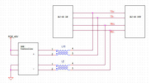
3) How is power injected without access to the primary isolation transformer at the source side or destination?
     It seems to me that if you use another transformer that you would compromise signal integrity.
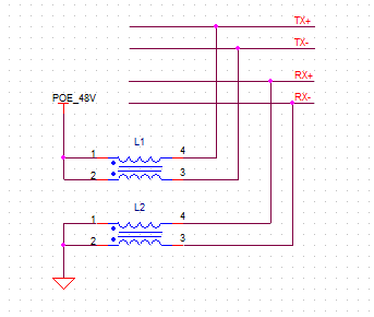
     Instead does one do something like the following with a CM choke?

  • Hi Daniel,

    I am currently looking into these questions, I will post an answer as soon as it is available. Thanks!

  • Hi Daniel,

    Thanks for your patience here. Please see my comments below:

    1. Unfortunately 24V through the ethernet cable is considered non-standard PoE. Per the IEEE standard AF,AT,BT, the voltage is between 44V-57V of the PSE depending on the Type power level.

    2. Specifically, the standard requires isolation at the power interface. From a system design prospective this means isolation of the high PoE voltage so on the PSE design, this means the 50V DCDC that powers the PSE will be an isolated DCDC.

    3. Yes I've seen many designs with chokes on the PSE port to minimize EMI. In terms of signal integrity, the data transformers typically have common mode chokes on the data side of the data transformer to reduce the noise of the ethernet data.

    On the power injection into the power side of the data transformer, we use the center taps. This will look like a common mode signal for the power and differential for the ethernet data. I recommend looking at some of the training material in the link below that goes over the PoE architecture. Please let me know if this helps. Thanks!

  • Hi Darwin,

    Thank you for your help. My questions almost all resolved except for the following

    3. Yes I've seen many designs with chokes on the PSE port to minimize EMI. In terms of signal integrity, the data transformers typically have common mode chokes on the data side of the data transformer to reduce the noise of the ethernet data.

    We will design our own POE injector which has does not have access to the transformers at either end of the data signal chain. For example, a typical signal path would have an ethernet node with its PHY, transformer and connector and the other end of that path with its PHY, transformer and connector. We will inject power midspan without access to either of these transformers. In other words the signals are already referenced to the cable medium side of these transformers and we do NOT have access to a center tap of their windings because our power injector is somewhere in the middle. My question is this: do power injectors add another center-tapped transformer in order to in inject power or do they just do as I showed in my schematic above? If they another transformer, wouldn't that 3rd transformer degrade signal integrity, especially since its windings are not being driven directly by the PHYs? 

    Take for example, this product here. Do you know approximately what the implementation would be, not in terms of the power supply, but the actual power placement on the wire? 

  • Hi Daniel,

    Unfortunately I don't know how exactly that EE is connected; however, in order to be compliant, the power should to through the center taps and not directly on the 4 pairs. I believe midspans will approach it this way with adding the data transformer in the EE. I don't believe it will degrade the signal integrity. We have taking the EVM for example, and the data port to a data only switch then we connected the PoE output of the EVM to an IP Phone and the IP Phone worked fine with no issues. I believe midspans would behave the same way similar to the EVM architecture.

  • Darwin,

    Thank you. I took a look at the eval board: https://www.ti.com/tool/TIDA-050026-23881

    And I did see that it takes an input and uses another ethernet transformer to inject power. If that works, that is good
    enough for me.

    Many thanks.