This thread has been locked.

If you have a related question, please click the "Ask a related question" button in the top right corner. The newly created question will be automatically linked to this question.

TPS23861: TI's power scheme LM5022+TI's PSE controller scheme TPS23861 constitute the PSE switch CE exception

Other Parts Discussed in Thread: PMP20588, LM5022, TPS23861

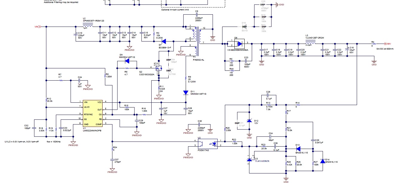
This is a schematic drawing that fully refers to TI's reference design, TI's drawing number is PMP20588.Web link: www.ti.com.cn/.../PMP20588

The change is that the transformer is changed from PA6582-AL to 25SEFD-0901DJNL.

Here are the questions:


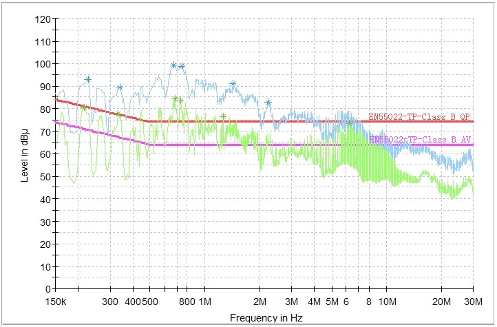
Now using TI's power supply scheme LM5022+TI's PSE controller scheme TPS23861 design of the 4-port PSE switch, CE (conduction) and Re (radiation) test results are as follows, among which CE exceeds the index more, we hope TI can provide relevant test data and improvement suggestions.The transformer is 25SEFD-0901DJNL(PN:YEL731R009).


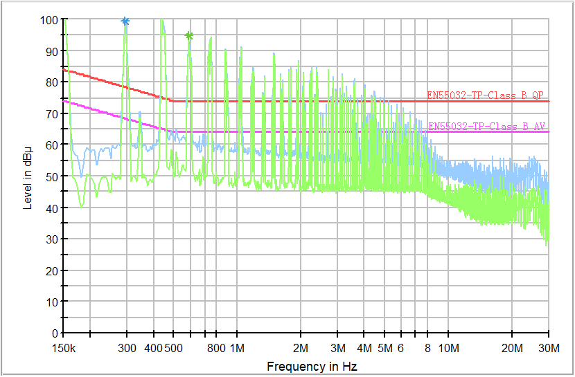
CE: PSE power supply works, and PSE port has data, other network port CE curve

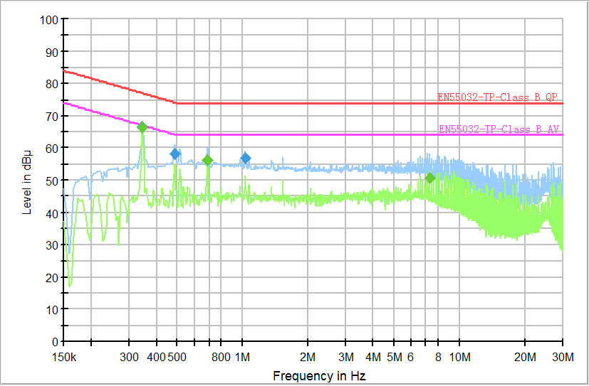
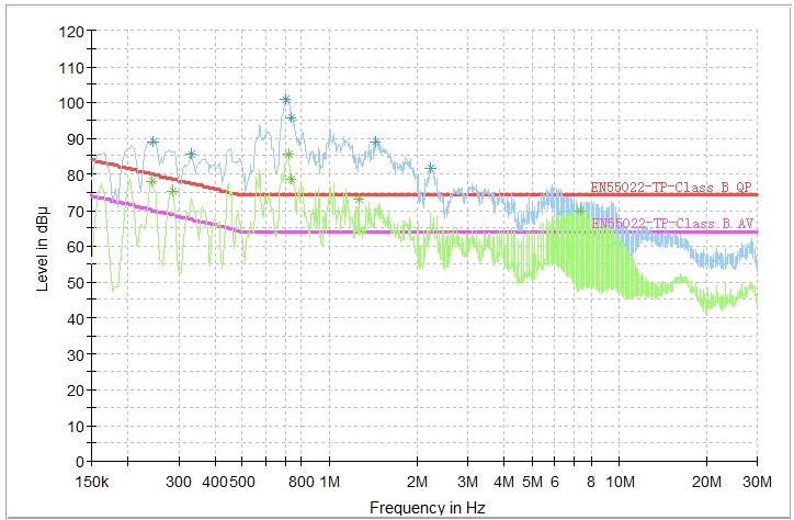
CE: PSE power supply works, but PSE port has no data when other ports have CE curves
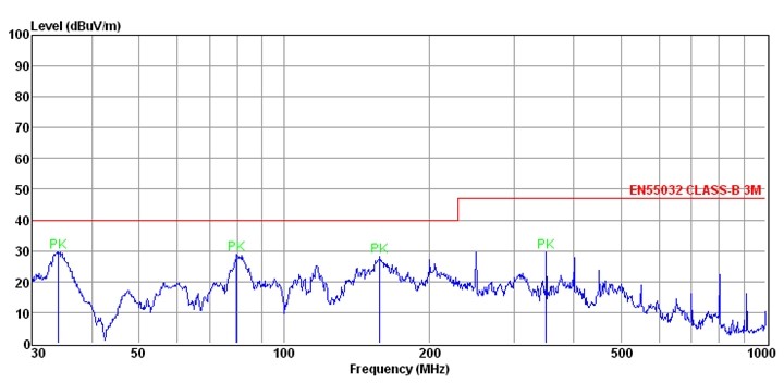
RE

  • Hi User,

    Are you measuring EMI at the power supply input or at the PSE's RJ45? Do you have schematic of your design for reference? Thanks!

  • We measured EMI at RJ45, and the design schematic diagram was copied according to the official document of TI. The reference figure is PMP20588. There is a difference at the power input, RT has been adjusted, and it is 150K, and the switching frequency is about 115K

  • Hi User,

    Thanks for the input. The PMP20588 is a reference design to show a proven power solution. EMI is more of a system level spec that will vary greatly with layout, component selection, component placement etc, at the end equipment design level.

    I do see that the reference did make some accommodations to add some filtering to help with EMI.

    Have you tried putting a larger common mode choke at the PSE port to help with the lower frequency EMI? You can also add ferrite beads in series (high side and low side) to help with the higher frequency EMI.

    Please let us know if this helps. Thanks!

  • I changed RT back to113KΩ to make the frequecy meet to 150KHz,then I shielded  the transformer by copper foil. The results of the RJ45s without PSE changed good, but the RJ45 with PSE was still bad. QP and AV were up to 100 dBu, and the frequency of the higher points were integer times of 150KHz, that meeting the switching frequency of LM5022.

    I also added a common mode choke(TDK:ACM7060-701-2PL) at the PSE port, then palced a 1nF cap befor and behind the common mode choke. But that seemed useless.

    RJ45 with PSE + Transformer Shielded.

    RJ45 without PSE + Transformer Shielded.

    Waveform at  Pin7 of Transformer:

    Waveform at  Pin3/4 of Transformer:

  • Hi User, i'd like to double check your EMI setup. Are you using a PoE LISN? And the PSE is connected to the coupled side while the PD is connected to the decoupled side? It's interesting the common mode choke made no difference. Have you tried in increasing C30? And can you try removing C49 to minimize the common mode current? The lower frequencies are usually related to the common mode current and I want to make sure the components I highlighted make a difference.

    Lastly, for your PoE system, what nodes are connected to the earth ground of the EMI setup? Thanks!