This thread has been locked.

If you have a related question, please click the "Ask a related question" button in the top right corner. The newly created question will be automatically linked to this question.

TPS55340: Ultra low ripple Boost Converter

Part Number: TPS55340
Other Parts Discussed in Thread: TPS61175, TPS55288, TPS61378-Q1, TPS61170, TPS61391, TPS7B4253-Q1

Hi,

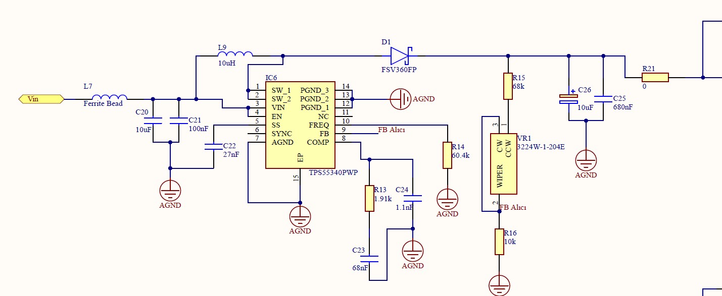
We are using TPS55340 for boost converter. During the test, it has very high ripple for our design. Our schematic is shown as below, and we designed TPS55340 using webench design. Our input voltage is 12V, and we want the output between 10-35V. In our design our ripple is around 100mV with 750kHz frequency.

We are demanding ultra low ripple boost converter. The output ripple does not exceed 100mA. Also, the operating current is around 30mA. Can you suggest as much as minimum voltage ripple boost converter IC?

Is there any minimum number of capacitor on the output of the boost converter for low ripple? When we use more parallel capacitor on the output, what effect can be occur? 

If we should use more capacitor to the output, should it same value or not? 

  • Hello Ozancan,

    Would you please re-attach your schematic? It got lost somehow.

    Please check if you are seeing a behavior as in Figure 22 of the datasheet, then the load is too low for entering continuous conduction mode for higher efficiency at light load. This increases efficiency, but increases ripple as well.

    If you are ok with a lower efficiency for getting a lower ripple, you should select a converter that permanently switches independent of the load, e.g. TPS61175.

    BTW, you will not get 10V on the output with a 12V input on a boost converter. Boost converter always regulate the output to a higher voltage. If you need to regulate up and down, I recommend to have a look at buck boost converters like TPS55288.

  • Hi Ugur,

    before looking into the detail of the current solution, I want to double check with you if the VOUT is regulated at 10V even when VIN =12V.

    if yes, the boost topology is not selection. instead, buck-boost or SEPIC should be selected.

  • Hi,

    The Vout does not have to be 10V. We can test the range between more than 12V to 35V. The main concern is minimum voltage ripple. The system should be as far as stabile.  

  • Hi, 

    You suggested that TPS61175. We are not considering the current or other efficiency stuff. We are only considering minimum ripple.

    1) Is it the best low ripple performance boost converter?

    2) What is the ratio of ripple when compared between TPS55340 and TPS61175? 

    3) When we add LC filter at output, what effect does occur on our system?

    4) When we check TPS61175, what should be duty cycle and center frequency for minimum ripple? 

  • Hi 

    is the C26 aluminum capacitor or ceramic capacitor? if former, please change it to ceramic cap and add more ceramic capacitor 

  • Hi Jasper,

    Thank you for your suggestion. We will change it. By the way, can you respond other questions that I asked.

  • Hi Ozancan,

    let's focus to optimize the performance of TPS55340 firstly. the 100mV ripple is not very hard. 

    the lowest ripple device could be TPS61378-Q1 if the output voltage is not very high

  • Hi Jasper,

    The ripple is very crucial for our project. We are using the output voltage for the supply voltage of the PIN photodiode. In other words, boost converter are used for LIDAR system. Therefore, the ripple is very critical. The ripple of the supply voltage can affect the PIN photodiode (receiver). As I said before, the ripple should be minimum as far as possible. 

  • Hi Ozancan

    is the maximum voltage 35V? what is the minimum output current? do you still need low ripple at the minimum loading? 

    if the ripple is very critical, you can consider to add a LDO between the boost and the loading.

  • Hi Jasper,

    The maximum voltage is around 30V. 

    The minimum output current is approximately 20mA.

    We are using boost converter for supply voltage of laser diode and PIN photo diode. We can add two boost converter for each one of them.

    Can you send the schematic for adding LDO between the boost and the loading? We could not understand clearly.

  • Hi Ozancan,

    the requirement is not easy to meet. the TPS61170 should be the closest solution, but I can't sure if it is doable because the VIN, VOUT and IOUT condition greatly impact the ripple performance, so I would suggest you to apply EVM to evaluation.

    another solution is the TPS61391, which integrate the boost and a filter circuit, but the input voltage should be lower than 5.5V, and output current can't be such large. 

    about the LDO, I refer to the a solution such as TPS7B4253-Q1. the input of the LDO is the output of the boost and the output of the LDO is the loading.