This thread has been locked.

If you have a related question, please click the "Ask a related question" button in the top right corner. The newly created question will be automatically linked to this question.

TPS2372: PD consumption and TPS2372-4RGWR

Part Number: TPS2372
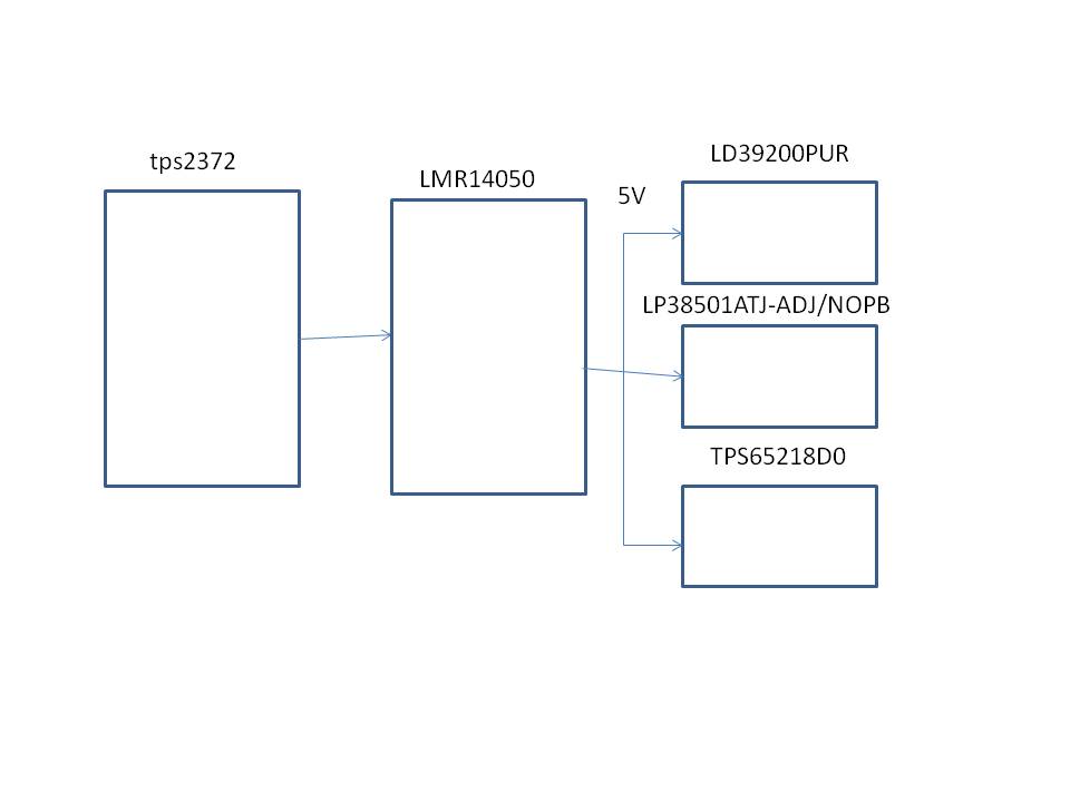
Other Parts Discussed in Thread: TPS65218D0, LMR14050, , TPS23731EVM-095, TPS2378

Hi TI!

I am designing a PoE device (PD) based in TPS2372-4RGWR. The design has an base consumption of 1.4A with consumptions peaks of 5A / 0.6ms every 4.5 ms and 2.4A / 5s every 5 minutes.

The TPS2372-4RGWR and output capacitor 100 uF are enough to supply the system?

If no, any suggenstion? Please,

Thank you very much. 

Best regards. 

  • Hello, 

    What is the output voltage?

    Are you talking about using the TPS2372-4EVM-006? Or is there another DCDC?

    Generally the minimum output capacitance is as follows for a flyback:

    If this post answers your question, please indicate so by marking this thread as resolved. Thank you.


    Regards, 


    Michael P.

    Applications Engineer

    Texas Instruments 

  •  Hello Michael Pahl


    Sincerely thank you very much for your answer and helph.


    In my design the idea is:
    tps2372 + LMR14050 (5V output) + others regulators and PMIC (LD39200PUR + LP38501ATJ-ADJ/NOPB + TPS65218D0) acoording the attached image imeage.

    The Iidea is to get 5V to supply others regulators according the attached image.

    Yes, I refering to the TPS2372-4EVM-006. I want to port the reference design TPS2372-4EVM-006 to my custom design.

    My question if is the tps2372 and Cbulk = 100 uF can be support currents peaks of 5A / 0.6ms and 2.4 A / 5s. Because according the datasheet the tps2372 can be deliver only 2.2A

    Please coud you give me a reference of the Cout equation.
    I am not clear about Dmax and Isec_step.

    Sincerely, thank you very much. Best regards. 

  • Hello,

    Understood. At TI, we call that capacitor the "input bulk cap" since it is on the input side of the DCDC. This capacitor's value is actually regulated by the PoE standard because it has to handle transients on the ethernet cable, but also startup fast enough within the inrush time limits. 

    So for a Class 8 power design (70W), the range of acceptable capacitors is 100uF - 200uF. 

    When you talk about 5A peak currents, if that is at the 48Vinput rail, that would be 240W. That is way past the 90W IEEE802.3.bt standard limit -- so your concern isn't the capacitor but any PSE supply you buy will not be able to supply that current. And the TPS2372 cannot handle that power, so you would not be able to do this. The current rating 2.2A is in reference that the current has a return path to the ethernet cable, and that is through the internal pass FET between VSS & RTN. But 5V at 48V is way beyond this and the PoE standard, and no capacitor is going to change this.

    Additionally, the DCDC stepdown converter chosen has an input voltage range of 4V-40V. The PoE input rail is 37V-57V. So unless you 100% control about the PSE used, then this DCDC will be broken when a PSE is connected and uses higher than 40V on the rail. Nearly all PSE's deliever power at higher voltages in the range since it creates less loss in the cable. 

    If you need 5A at 5V, this is a different conversation, let me know if I understand your project correctly. 

    If this post answers your question, please indicate so by marking this thread as resolved. Thank you.


    Regards, 


    Michael P.

    Applications Engineer

    Texas Instruments  

  • Hello Michael Pahl
    Sincerely thank you very much for your clear and detailed answer.

    I need 5A at 5V.
    Then, in this case the power is P = V*I = 5V * 5A = 25W.
    Then, in this case the current in the internal pass FET between VSS & RTN must be I = P / V = 25W / 48V = 0.53 A.

    Please the previous claculus are ok or I am confused?

    Yes, effectively the DCDC step down converter support only 40 V and isn't good for PoE (57 V). It was only a ilustrative reference accordingd the previous design without PoE. Of course, thank you very much for your profesional and correct evaluation and suggestions.

    Sincerely, Thank you very much. 

    Best regards

  • Hello,

    Oh, yes 5V/5A is much different. We call that Type 2  or Class 4 power. So 100uF would actually be too big. The range instead should be 33-47uF. 

    Yes your calculation is correct, you can use much lower power products. 

    I would suggest looking at our newest parts that support this power level. The TPS23731EVM-095 uses a DCDC with a 5V/5A output. You could copy the design directly for your system. 

    If you already have your DCDC figured out/set, you can use our Class 4 standalone PD: TPS2378. Unless there are features in the TPS2372 that you want like autoMPS, I would recommend the TPS2378 to save on cost. 

    If this post answers your question, please indicate so by marking this thread as resolved. Thank you.


    Regards, 


    Michael P.

    Applications Engineer

    Texas Instruments 

  • Hello Michael Pahl,

    Sincerely thank you very much for your perfect analys, help and suggestions.  

    A happy day for you. Best Regards!