This thread has been locked.

If you have a related question, please click the "Ask a related question" button in the top right corner. The newly created question will be automatically linked to this question.

BQ76952: Ts2 use for shutdown wake up

Part Number: BQ76952
Other Parts Discussed in Thread: ISO1540

Hi team,

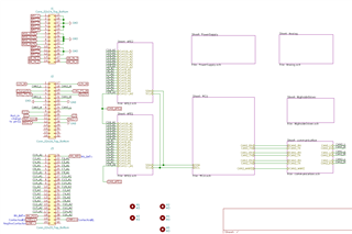
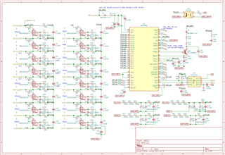
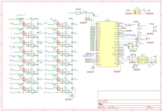
My project using 2xbq76952 stacking together to manage 24 battery cells, and both bq76952 using isolated i2c (ISO1540) to communicate with host MCU. Now I have some problem to enter shutdown mode using I2C command,  the hardware using optocoupler which the primary side using MCU to control the second side connect or disconnect TS2 to VSS,  as I expect to using MCU to wake up each bq76952. There are some problems:

1. some time when I send the shutdown conmmand, the device won't enter shutdown mode, i read out the battery status register (0x258d) which indicate the device receive the shutdown but not perform it. Why this happen? By the way the LD pin of device is connect to VSS through an 1k resistor. I measure the TS2 pin which is 0V.  Dose TS2 below VWAKEONTS2 cause the device not enter shudown mode?

2. I notice the manual mentioned TS2 is default set to 18K pull up by default and i also try to config the TS2 pin to ADC input , but why TS2 is still 0V.

  • Hi Yao,

    1. It sounds like the part has some condition which is preventing shutdown.  Check the charger detection setting  and the condition on the TS2 pin.  See the technical reference manual section 7.5. You have LD pulled down, be sure TS2 is floating so it can be pulled up to the 5V wake condition, yes TS2 held below VWAKEONTS2 will prevent shutdown mode.

    2. When TS2 is used for temperature measurement it is pulled up only for the measurement.  When measured with a meter it will normally show 0 V.  Check the pin with an oscilloscope. 

  • Hi WM5295,

    The TS2 is not floating, but connected to VSS through the second side of optical-coupler (TLP291), I suspect there is something wrong with the design using this coppller. The device can shutdown anytime if I remove this coupler.

    There is something still confuse me, if I send the RESET() 0x0012 command first and send SHUTDOWN(), it works even with TLP291 soldered.

    Another thing is the shutdown command  is working only send once, is that nomal? I believe the device is in FULLACCESS MODE .  I program the OTP just enable REG0  and REG1(5V), which Reg1 used for ISO1540 power supply and I2C pull up. The Reg1 indicator LED will turn off when i send shutdown command only once.

    The voltage between TS2 to VSS is around 3.6V during shutdown mode, is this normal?

    please see the attached schematic.

  • Hi Yao,

    RESET will clear the configuration of the BQ76952, without writing the OTP it will turn off the REG1 and REG2 if used.  You mention having written OTP with regulator settings, so after RESET the REG1 and REG2 should still be present, but other settings not in OTP will be lost.  There may be some influence from other settings although that is not clear.

    With the device unsealed a single shutdown will shut down the part although a second shutdown will skip the delays as described in the technical reference manual section 7.5.

    TS2 will pull to 5V when shutdown, and look for a voltage below VWAKEONTS2 to wake up.  The pull up to 5V is high impedance.  If the optocoupler has some leakage it will pull down the voltage, or if a meter with a moderate source impedance is used it will also pull down the voltage.  So 3.6 V may be normal for your measurement, it should not prevent shutdown or wake the part.

    An observation in the schematic:

    • The PACK pin connects to BAT+_A2 which is cell 16.  PACK pin should connect through 10k

  • Dear WM5295

    About shutdown commands not work, it seem like the leakage current of the optical-coupler, after change to anther model, it works. Thank you!!

    Now I meet another new problem really make me head pain... as I mentioned previous, my project using 2 bq76952 stacking together to manage 24 cells, the lower bq76952(may call AFE1) burned several times, but AFE2 work fine. As I connect all batterys onto BMS PCB, both AFE working fine, and I can read out cell voltage. But when use digital multimeter measure the battery cell(not on this bms board), just only one probe connect to cell 1's negative post, the chip damaged immediately, this happen more than one time so It's hard to blame static electricity. About AFE1.sch, it also using to measure the total package voltage and the divided voltage into chip ADC is less then 1.5V.  I will post my schematic and please help to check.

    Regards,

    yao

  • Hi Yao,

    That is really disappointing. ICs fail in different ways, in my experience holes blown in the package are usually an overvoltage with significant current capability.  I don't recognize an issue from the AFE circuits. You have isolators for the communication lines, you might check all the reference levels of the other interface circuits, but it does not seem like those should change from a meter probe connection unless it biases a second point in the circuit to an GND.

    One thing I don't recognize is how the GND_AFE2 connects to the C16_A1 and C1N_A2.  Those must be at the same DC potential.  You are more familiar with the circuit and will likely recognize it. 

    Please let us know what you find.