This thread has been locked.

If you have a related question, please click the "Ask a related question" button in the top right corner. The newly created question will be automatically linked to this question.

UCC21732: OC pin connection of 2 parallel FETs.

Part Number: UCC21732

Hello.

I am considering using UCC21732 to drive two FETs connected in parallel.
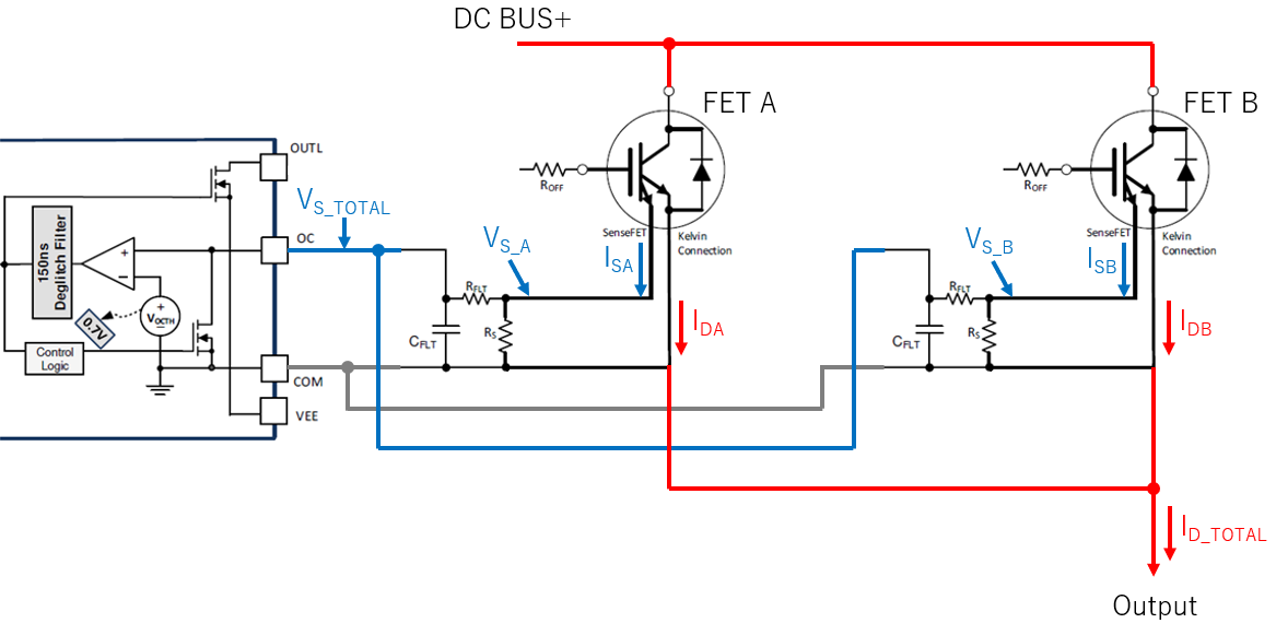
If each FET has a Sense-FET pin, would you tell me the recommended way to connect it to the OC pin of UCC21732.

I would like to consider a circuit that can be detected by the OC pin regardless of whether either of the FET is overcurrent alone or both FETs are overcurrent.

In this condition, in case of the circuit model in Figure 9-8 in the datasheet SLUSD77A, I can't connect 2 Sense-FET pin parallelly in point of after Rflt resistor, is it correct ?

Thanks and Best Regards.

  • Hi, 

    Are the drains of these Fets connected? In that case, the VDS and thus drain current and senseFET current will be virtually equal in both. 

    There are some solutions, but each one has tradeoffs. 

    Option1: Only connect ONE SenseFET to OC pin. 

    If the FETS are in parallel with drain, you could short the snsfet connections of the IGBT at the shared node of Rs / RFLT.

    In a short circuit case, both IGBTs will experience the same current which will make the sensefet output approximately equal. Following this reasonsing, you could even just take Sensefet input from just 1 IGBT rather than both, as this will tell the story for both. 

    Option2: Short both SenseFET

    If you are truly concerned that only ONE Fet will short circuit with connected drains e.g. if one catastrophically fails but other one doesn't, keep the RS value the same so that the OC will trigger if just ONE FET goes into overcurrent. Of course, ensure that an OC senseFET current will not exceed OC pin ABSmax (you could also do this with a zener if this is a potential Issue)

    The issue with this is that this is that, lets say you have OC set to trigger at X amps. By keeping resistor the same, the OC will trigger if 1 FET fails, trigger at X amps. But it will also trigger for the more likely case that BOTH go into OC at X/2 Amps each. Since both going into OC simulataneously is more likely, I would actually suggest to halve the value of the resistor you normally would have so that it triggers when Each are at X amps. 

    My logic from above is that if drains are shorted, if only ONE goes into OC there must be a catastrohpic failure and trigger at 2*X amps might be more acceptable in that case. 

    Option3: Add discrete comparator + logical OR function. 

     You could add a discrete comparator for each FET and directly connect output to OC pin through a logic OR function (either by a Logic gate or by open-drain ouput/pullup) This should still maintain deglitch. This doesn't have the drawbacks of Option2, but it will add area and bom cost. You will also need an external reference to each comparator in this case as well. 

    Option4: Use DESAT detection instaed of OC. 

    There is also the option of Using DESAT rather than OC. If DESAT style protection setup is used, you simply connect all drain to the D_HV diode, as their drain voltage is identical during desaturation anyways. Since you are using sensefet this may not be desired. 

    If this answers your question, please let me know by pressing the green button. 

    Best

    Dimitri

  • Hi,

    Thank you very much for your quick answer. And thanks also for many solutions you gave me.

    Option 2 or option 3 is good for me.

    In case of option 2, let me confirm my theory is correct or not please.

    Regarding the attached picture, can SenseFET be considered as a current source ?

    If yes, and if I want to set OC trigger for 100A total (50A for each FET), I can select 700 ohm for each Rs resistor. Is it correct ?

    Each FET's Ioc_th = (Vocth / Rs) * N = (0.7 V / 700 ohm) x 50000 = 50A, when N = 50000

    Total Ioc_th = 50A x 2 = 100A


    In this case, if unbalance current through (ex. Ida = 25A, Idb = 75A) was occurred, Vs_total can be calculated as following ? And it can be triggered OC. Is it correct ?

    Vs_total = (Vs_a + Vs_b) / 2 = (0.35 V + 1.05 V) / 2 = 0.7V

    Vs_a = (25 A x 700 ohm) / 50000 = 0.35 V
    Vs_b = (75 A x 700 ohm) / 50000 = 1.05 V

    And if another unbalance current through (ex. Ida = 25A, Idb = 50A) was occurred, Vs_total is not enough to trigger OC. Correct ?

    Vs_total = (Vs_a + Vs_b) / 2 = (0.35 V + 0.7 V) / 2 = 0.525V

    Vs_a = (25 A x 700 ohm) / 50000 = 0.35 V
    Vs_b = (50 A x 700 ohm) / 50000 = 0.7 V

    Best Regards,

  • user3335028 said:

    Regarding the attached picture, can SenseFET be considered as a current source ?

    Roughly. Its more of a current mirror as its drain current is NOT totally independent against the source voltage shift. 

    user3335028 said:

    In this case, if unbalance current through (ex. Ida = 25A, Idb = 75A) was occurred, Vs_total can be calculated as following ? And it can be triggered OC. Is it correct ?

    Vs_total = (Vs_a + Vs_b) / 2 = (0.35 V + 1.05 V) / 2 = 0.7V

    Vs_a = (25 A x 700 ohm) / 50000 = 0.35 V
    Vs_b = (75 A x 700 ohm) / 50000 = 1.05 V

    Correct on both, roughly. Note that if there is such a vast different in currents, some current will pass thru 2xRFLT to the other sense voltage node. 

    With this implementation, if the SUM of the currents I_SA and I_SB is 100A or greater it will trip OC, or said another way, the average current in each FET should be <50A or it will trip OC. One could be 10A one could be 90. One could be 0 the other be 100A. The way you have implemented is actually eliminating some issues which i mentioned in my initial response. 

    I would remove one CFLT and keep both RFLT (this is a requirement to average the voltage VSA and VSB). 

    CFLT and RFLT placed close to OC pin. 

    Note that such a vast different in drain current is a corner case and means one of the FET is broken. The advantage of your implementation is that if later you prefer to just take sense current from only one fet, you only need to remove a couple resistors from the board without changing any of the other passives values. 

    Please let me know if any additional questions. 

    Best

    Dimitri

  • Thank you for your prompt answer.

    Understood.
    I think I can start the circuit design.

    Thanks again for your excellent support!
    I will proceed this thread to resolved stage.