This thread has been locked.

If you have a related question, please click the "Ask a related question" button in the top right corner. The newly created question will be automatically linked to this question.

LM3914: Battery monitor design for 12V to 14V

Prodigy 130 points
Part Number: LM3914

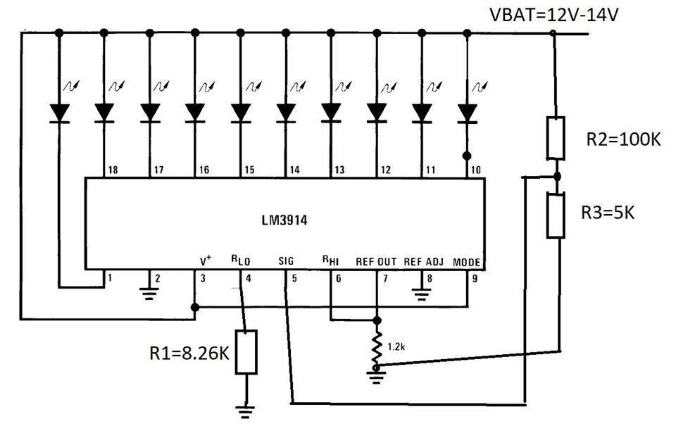
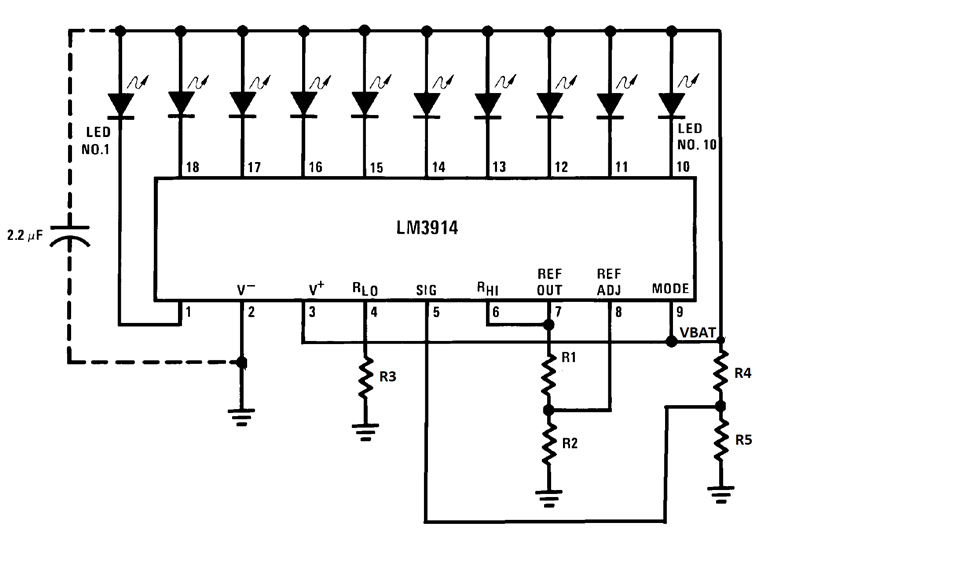
Please provide design for below battery indicator requirement :

Monitoring range : 12V to 14 V

1 LED should ON at when battery voltage is 12V

10 LED's should ON at when battery voltage is 14V.

If any ready design please provide.

Also provide the design calculation for same

  • Hello,

    Thank you for your post and patience. Due to some E2E maintenance recently, we were only able to see your post now. I will review datasheet calculations for your requirements and respond with feedback by tomorrow.

    Kind Regards,

    Liaqat

  • Hello,

    I have modified a circuit from the datasheet for the requirements you mentioned in your post. Please see schematics below. You should have a divider network to scale down the input voltage range for LM3914 input buffer. For the schematics shown below, for VBAT of say 11.9V, all LEDs will be off and R3 will have a voltage of 0.566V. So R1 should have 0.566V when overall voltage across the whole divider ladder is 1.25V. Since sum of internal ladder resistors is 10K ohm, R1 needs to be 8.26K to provide a divided voltage of 0.566 across it. This should meet your requirements of 1 LED on when VBAT is 12V and all LEDs on when VBAT is 14V or greater.

    Kind Regards,

    Liaqat

  • Thank for Reply. 

    After building above circuit, observations as:-

    1. for 11.9V - all LED OFF (Vtg across R3= 0.566V, R1= 0.565V)

    2. for 13.4V - D1 LED ON (R3=0.638V, R1= 0.565V)

    3. for 14.8V - D1,D2 LED ON (R3=0.704V, R1=.565V)

    ....

    9. for 24.9V - D1 to D9 LED ON (R3= 1.857V)

    10.. for 26.3V - D1 to D10 LED ON (R3=1.25V)

    which does not satisfy the requirement.

    Please provide solution for updated requirement as(not for 12V to 14V)

    Updated range : 11V to 13.7V

    1. For 11V input D1 LED should ON

    2. For 13.7 input D1 to D10 all LED Should ON.

    Waiting for Your response.

  • Hello,

    I am a bit occupied with some other support tasks right now but should be able to look into this and provide any feedback by Friday US time. Thank you for your patience.

    Kind Regards,

    Liaqat

  • Hello,

    Thank you for your patience. I looked into it and with ranges you mentioned above, I think we will have to use a slightly complex circuit to adjust the reference voltage to an appropriate range. Please use the modified schematics shown below (modified from figure 1 of the datasheet) and if you use the component values of R1=2K, R2=5.3K, R3=39.1K, R4=20K, R5=10K, you should be able to cover the range of 11V to 13.7V.

    This will work as follows: With VBAT of slightly below 11V (say 10.9V), scale down divider resistor R5 should have a voltage of ~3.63 and for VBAT of 13.7V, R5 should have a voltage of ~4.56V. Combination of resistor divider R1/R2 will adjust the reference out to ~ 4.56V to account for this. Since this 4.56V is impressed across the internal resistor divider of LM3914 + R3, resistor R3 calculates to be 39.1K, using the voltage divider formula, so that voltage across it 3.63V when VBAT is ~11V.

    Please use schematics below for this design.

    Kind Regards,

    Liaqat