This thread has been locked.

If you have a related question, please click the "Ask a related question" button in the top right corner. The newly created question will be automatically linked to this question.

TLC59711: LED flickering when turning on unused output & To use or not use LED resistors?

Part Number: TLC59711

Hello,

We are testing the TLC59711 for our applications but we are experiencing some problems.

For now, we only have 2 RGB LEDs connected to Out0 and Out3 and if we try to turn on the other outputs the LEDs start to flickering.
We have also assembled a second board with a new LED driver with LEDs connected to outputs Out1 and OUT2 but the same problem happens. 

Is this normal behaviour? The LED driver appears to be working fine if we do not turn on the unconnected outputs. We realize this problem by turning on by mistake the wrong LED output in our application. 

In addition to that I have seen in the forum, that other users connect the LEDs with a resistor but the Typical application circuit diagram in the Datasheet does not include the LED resistors. Is there any benefit or inconvenience if they resistors are used? We have tested both scenarios and they seem to be working ok.

Thanks
Daniel

  • Hi,

    I am a colleague of Daniel's. Here is what else we tried.

    We connected RGB LEDs to all outputs of the tlc59711. We can control each channel individually and reliably. Global brightness is set to 127,127,127, and for now we are just switching LEDs on (65535 on their channel) or off (0 on their channel). All this works so we have no reason to suspect any issue with data communications.

    However, if we switch on 8 channels simultaneously, all the LEDs that are on start to flicker. The flickering gets worse the more channels that are switched on. It doesn't seem to matter which channels are enabled, just that the flicker starts with the 8th channel.

    What could be a cause of this flickering? And would the issue be expected to be particularly bad in the case where an unconnected channel was switched on, as we saw last week?

    Thanks

    Tony

  • Hi Daniel and Tony,

    Sorry for late reply. Could you help to capture a plot for VLED / VCC / VOUT for LED connected channel / VOUT for unconnected channel, while the LEDs start to flickering? And could you help to share your schematic?

    Normally the open unconnected pins would not have any influence on LEDs, since the outputs are current sinks and cannot work if there is no pull up connection.

    For the structure cascades LEDs with a resistor, normally it is used in inconstant output device, to set the output current. For constant current device like TLC59711, the resistor can reduce some power dropped on output pins, which improves thermal performance.

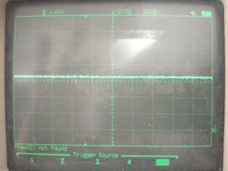
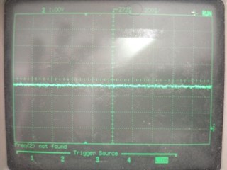
  • VCC shows occasional spikes above 6v if any LEDs are on. It seems to me these spikes are more frequent and a bit bigger the more LEDs are on, but that's just anecdote, the old scope I have here is not picking up any frequency data.


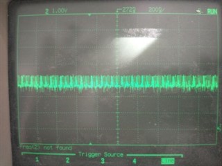
    VOUT on the connected channels seems to change between ~3.3v when the LED is off, and ~2.5v when it is on. I am guessing these levels are related to the voltage drop across the LEDs? I don't understand the electronics behind the constant current outputs. And when the LEDs are flickering, I do see VOUT jumping between these levels:

    My setup now has all the channels with LEDs installed so I cannot measure VOUT on unconnected channels.

    The schematic I don't have; but we are based on the first example circuit from the datasheet, using the internal regulator with VCC=5v.

  • Hi Tony,

    What power source you used, DCDC or external power supply? The VCC supply seems unstable that have large spike during operation. Could you parallel more capacitor between VCC and GND to see if the spike can be smooth?

    Do you have 2 channels in your oscilloscope can sample both VCC and VOUT to see if the spike comes when output pin enable?

    Yes the VOUT levels are related to forward voltage across the LED. As you can find I-V curve in LED datasheet, forward voltage cross LED is exponential with forward current. When LED off, there are still around 1uA leakage current through LED and channel. Forward voltage in small current is 1.7V in your case. And when LED illuminated the forward voltage is around 2.5V. What PWM value you set for this channel? It looks like normal PWM behavior. Could you help to try set it full on to see if it is still 'jumping'? 

  • I think 5v is from DC-DC power supply on our main board. I'm not the hardware engineer, I'm firmware so I don't know about the power circuit but it certainly isn't an external supply. There are smoothing capacitors on the board but our development hardware is on the end of ~10cm cable soldered to the board so maybe too far?

    The spike on VCC comes repeatedly, certainly not just when I turn a channel on or off. Also if it was coming once per 65536 cycles of the internal GS clock or something like that, I think my scope would have picked up the frequency (although it is a very old second hand scope, maybe that function is broken). I'll try to scope both channels at once and see if there is some correlation.

    I don't think the flickering graph shows PWM behaviour. The LED was set full, and I did not change the state of the LED I was scoping at all between the LED-on plot and the LED-flicker plot. All I did was turn on some different channels.

  • I scoped VCC and one of the outputs, while it was flickering.

    Top trace is VCC (1v / division)

    Bottom trace is VOUT (2v / division)

    Clearly the spike on VCC is also present on VOUT - also a lot of noise on VOUT and VCC before the spike, and less after.

  • Hi Tony,

    Sorry for unclear statement before. What I said VOUT is the voltage dropped on output pin.

    Is there an external 5V power supply in your lab? We could do a test to see if the flickering issue was caused by insufficient VCC drive capability.

  • Hi Wu,

    I understood what you meant by VOUT. In my plot from last night, the lower trace is the output of one LED port, with the LED turned on, and many other LEDs turned on also so that all the LEDs were flickering.

    You can see the spike on VCC ends up on VOUT too, and also the noise on VCC. So I think yeah, maybe this is a power problem. I will try with a bench supply.

  • Hi Tony,

    OK I misunderstood the waveform before.

    Yes you could try using bench supply to provide VLED. What is the IREF and current setting for every channel? We can calculate a peak current when all channels open.

  • I tried with a bench supply but the problem was worse, not better. Now the LEDs flicker is 5 or more are switched on, and after 6 or 7 the device resets and turns them all off. The scope trace shows that the voltage near the device is noisier than before. I guess maybe because the leads from supply to tlc59711 are longer and there is no smoothing at the device.

    I will try getting some capacitors added to the development hardware but I won;t be able to do that until next week.

    Tony

  • Hi Tony,

    Regarding to reset issue. I think you could monitor voltage of VREG with VCC to see if the VCC ripple cause unpredictable UVLO action.