


Other Parts Discussed in Thread: LM3409
Hi all:
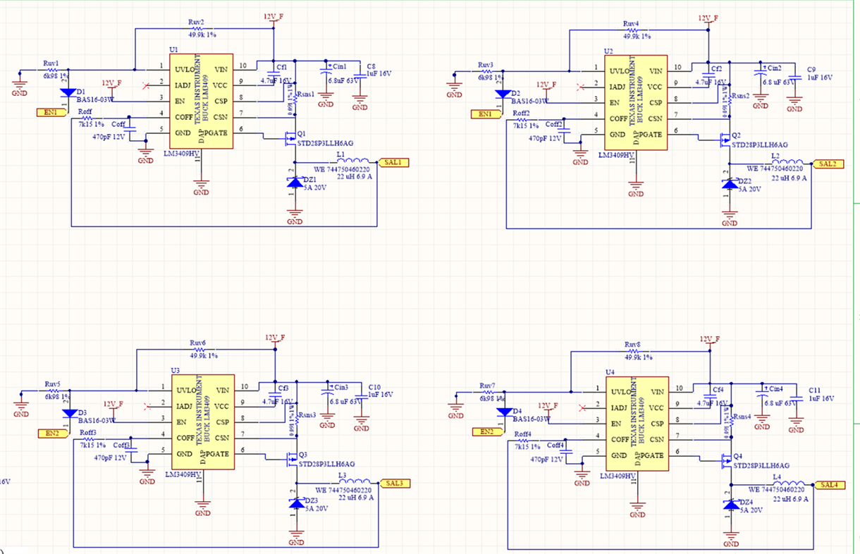
I have this 4 channel circuit using LM3409. 4 channels are exactly the same.
- The Led Load in each channel is: 4 leds in 2parallel string (2 led in series+ 2 leds in series). It is designed for 2.5 A por string (5 A per channel), Vin 12 V Vout 7. 8 volts
- EN1 and EN2 strobes channel 1&2 and channel 3&4, respectively. This signal is 100 Hz, 500us-2 ms width, depending on the application
I have the following problems:
- Signal too noise with big spikes in the four channels
- 4 channels are identical. However the behaviour of the 4 channel is different:
- Channel 1 (yellow trace figures 1 and 2 is sal1) is "almost " right (it does not reach the expected voltage). This could be just a problem of the calculations. But the output follows correctly the EN1 signal
- Channel 2 (Blue trace in figures 1 and 2 is sal2) is far from being right. It has a lower Intensity than expected (if we look at the expected voltage) and it has a slow slope that goes down sloothly even after the EN1 signal is off. In this figures, channel 1 and channel 2 are pulsed using EN1 and in theory the circuit is exactly the same
- Channel3 and Channel 4 (Blue&yellow trace in figure 3) goes in a different direction: the pulse width seems correct, but the signal shape is far from being right. EN2 is correct and exactly the same as EN1

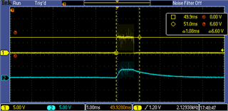
Fig 1& 2

fig 3
I know that maybe with this information would not be enough, but if someone could help that would be great. I dont know hy having the same 4 circuits, I have 3 different signals
I would say that treat each topic separately maybe could clear this. But right now for me this is kind of a mess
Regards
