This thread has been locked.

If you have a related question, please click the "Ask a related question" button in the top right corner. The newly created question will be automatically linked to this question.

TPS3106: Pull-up resistor of the RSTSENSE

Part Number: TPS3106

Hi All,

I have a question about TPS3106.

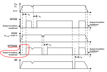
The pull-up resistor of the RSTSENSE pin is 330Ω as shown in the circuit diagram below.
Is there problem?


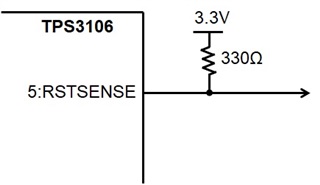
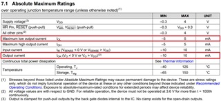
I set it to 330Ω because the output current value is 10mA.
I want to reduce the pull-up resistance as much as possible. Is 330Ω OK?
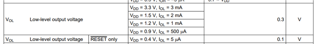
Or should I refer to the IOL (5mA) current?

Best Regards,
Ishiwata

  • Hi Ishiwata-san,

    You want to select the proper pullup resistor to ensure that you meet the VOL spec, across the VDD range, in the datasheet.  The recommended operating voltage for VDD is 0.9V to 3.6V.  Assuming that the pullup resistor is tied to the same VDD to the TPS3106, the calculation is:

    (VDDmin - VOL) / IOL ≥ (0.9V - 0.3V)/500uA ≥ 1200 ohms.

    Therefore, the pullup resistor must be greater or equal to 200 ohms to ensure VOL is met at VDDmin.

    Ben

  • Hi Ben-san,

    Thank you for your answer.

    The IOL you have listed is a test condition.

    With 7.1 Absolute Maximum Ratings, 5mA can flow.

      (3.3V-0.3V) / 500mA = 600Ω

    It will be at least 600Ω.

    Certainly, when starting up VDD, it is necessary to consider 0.9V, but 5mA can flow at 3.3V.
    Is my understanding correct?

    Best Regards,
    Ishiwata

  • Hi Ishiwata-san,

    Yes, the current I used is the test condition.  The absolute max ratings says 5mA which is the max amount of current the pin is allowed to consume.

    Yes, your understanding is correct?  Is speed a factor in the design of the application?

    Ben

  • Hi Ben-san,

    Thank you for your reply.

    RSTSENSE will drop at startup. (Pull-up resistance when dropping is 10kΩ)
    I think that it dropped in the Output Condition Undefined period up to VDD=0.4V.
    I want to change the pull-up resistor to improve this drop.


    I have additional questions.

    A 0.01uF capacitor is installed between the RSTSENSE pin and GND.
    Is there a problem with the capacity?


    By the way, I wanted to insert a diagram to ask a clearer question, but I couldn't.

    Best Regards,
    Ishiwata

  • Hi Ishiwata-san,

    Yes, /RSTSENSE will drop at when VDD > 0.4V.  See below:

    Adding a capacitor to the /RSTSENSE pin to GND will cause the switching edges of /RSTSENSE to have a RC time constant appearance to them.  Therefore, the rise and fall times of the switching edges will increase.

    To insert a diagram, there are pulldown menus at the bottom of the reply box. see below:

    Click on "insert" and choose "image/video/file"Click on "upload" and select the file that you want to use.  See below:

    I hope my explanation is easy and clear.

    Ben

  • Hi Ben-san,

    Thank you for your answer.

    Regarding the capacitor between GND.
    Are there any disadvantages other than the rise and fall times?
    For example, I think that the discharge current of the capacitor flows into the IC. Is that a problem?

    By the way,
    Thank you for your support in the attached matter.
    Cleared the cache and improved.

    Best Regards,
    Ishiwata

  • Hi Ishiwata-san,

    There is no issue having the capacitor on the output (/RESET) with TPS3106.  The only concern I have is what about the other IC that is using the /RESET signal.  Is the other IC okay with a slower rise and fall times?  

    Glad to be of help and I hope you can add images on E2E now.

    Ben