This thread has been locked.

If you have a related question, please click the "Ask a related question" button in the top right corner. The newly created question will be automatically linked to this question.

UCC28070: UCC28070 start-up in-rush current limit issues.

Part Number: UCC28070

Dear TI support teams:

I have designed an AC/DC converter using UCC28070. There is a start-up in-rush current issue. The design is:

CDR tied to VREF

RDM tied to GND

Current Sensing resistor is 26 ohm for both CSB and CSA.

PKLMT is set to 3V with two 6.8kohm resistors divider, plus a filter capacitor.

SS tied to a 4.7uF cap

PFC inductor is bypassed by a in-rush diode

NTC resistors have been implemented to limit the in-rush current.

The whole design is merely following the TI reference PMP4311 but with switching frequency 200kHz. All the other parameters are calculated with TI spread sheet.

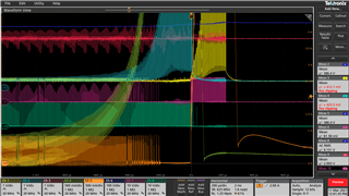
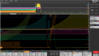
The in-rush current shoots upto 60A even when start up at no load or light load. The pulse on CSB and CSA are way beyond 3V on PKLMT, but no pulse-by-pulse limit took place!

Any help or suggestions are highly appreciated! Thanks

  • The attached picture illustrates my peak current limit issues on UCC28070.  This is captured during the transition from no load to 100Watts.

    In the scope capture: Ch1, Ch2 and Ch3 are voltage on ucc28070 pin CSA, CSB and PKLMT.

    Ch4 and Ch5 are two boost inductor current.

    Ch6 are boost output voltage.

    Ch7 and Ch8 are Vgs of MOSFETs for each boost converter.

    From this scope capture,  CSA and CSB are way beyond PKLMT (3VDC). But cycle-by-cycle current limiting is not happening at all. 

    To exaggerate this issue, I made the PKLMT to be 0.5VDC, see what will happen during no load to 100Watts transition.

    As the picture above shows, CSA and CSB are constantly above PKLMT (0.5VDC), and the in-rush current shoots up without any regulating.

    I guess that I must misunderstand the operation of ucc28070 completely. Otherwise, the simple peak current limiting comparator should work already.

  • hello,

    the PKLMT function is just to compare CSA/CSB signal with voltage on PKLMT, if CSA/CSB voltage is higher than PKLMT voltage, then GDA/GDB will pull load with about 60ns time.

    please double confirm whether the GDA/GDB respond correctly with PKLMT cycle by cycle.

    for the inrush current, if you add NTC(do not connect the relay) in series in the input circuit, is the in in rush current still achieve 60A?

    I am worry that during the in rush current moment, the relay already close and there is a big voltage between input voltage and PFC output (input voltage higher than PFC output voltage) during the no load start up.

     in this way the in rush current will be always there that can not be avoided.

  • The GDA/GDB didn't respond the PKLMT at all. Look at the images I uploaded. If GDA/GDB respond the over current, CSA/CSB won't keeping increasing until voltage loop error amplifier responded the output voltage bump.

    The scope captures are collected during the transition from no load to 100Watts.  At no load, the output voltage has been built up already (390VDC). The relay has been closed and NTC was out. The input voltage was less than 320VDC. So the The in-rush current happened purely due to the load step. By the way, these tests have been done on a lab DC voltage source. So you won't see the AC voltage cycles.

  • Hi

    "these tests have been done on a lab DC voltage source. So you won't see the AC voltage cycles" do you mean at this test, you are not using AC voltage in the input of PFC?

    UCC28070 can not support DC input voltage because it needs ac crossing signal for the whole control logic.

  • Thank you for your reply.

    The point here is not AC or DC source. I have been testing the AC/DC converter on both AC and DC sources. The behavior of ucc28070 is the same. The waveforms I shown here are collected on a DC source. Once I found the cycle-by-cycle current limit function is not working, I switched to a DC lab source to limit the input current for more safety.

    My point is that the cycle-by-cycle comparators failed to limit the FETs current. Unless, these comparators can't work under some circumstances, which I am eager to know. From the block diagram of ucc28070, my understanding is that they are designed to limit the in-rush current, when current loop demands too much current at load transition. 

    I used a function generator to generate a triangle waveforms then injected them into CSA/CSB. I observed the PWM stopped in a cycle-by-cycle way, when the triangle waveforms touched the PKLMT thresh-hold. So ucc28070 is functioning as design. But why it won't work when power it with some real current sensing signals?

  • Hi

    from your description, by adding signal to CSA/CSB can trigger the PKLMT to do cycle by cycle limitation but with real current signal on CSA/CSB, the controller can not work normally.

    My suspicious is the noise on the controller let the controller mis-behavier on its logic.

    can you use a separated DC source for UCC28070 controller VCC and separated Ground to controller's ground?

    I also suggest to compare the signal you inject into the CSA/CSB and the real signal when you do load transient to see if any difference.