This thread has been locked.

If you have a related question, please click the "Ask a related question" button in the top right corner. The newly created question will be automatically linked to this question.

TPS22810-Q1: is it suitable for my design?

Part Number: TPS22810-Q1
Other Parts Discussed in Thread: LM5060-Q1, TPS22810

Hello TI experts,

My customer consider TPS22810-Q1 for their products. but i am not sure this is suitable or not.

the schematic is as below;

1

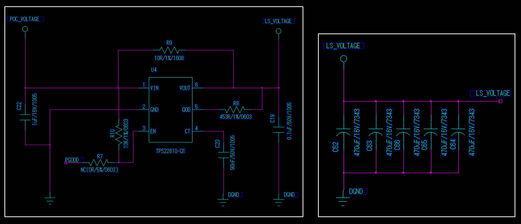
- VIN and VOUT are 12V, PWM signal. (1 cycle=33ms, duty cycle=3%)

- maximum continuous current is 12A.

I already found that continuous current of TPS22810-Q1 is 2A, but i am not sure that this 2A means same as what i am thinking.

could you check this condition is suitable for this device? if not, please recommend another device for this condition. Thanks.

Best regards,

Chase

  • Hi Chase,

    Power Switches are not meant for PWM. Your setup is for a 33ms time period PWm with a 3% duty. This mean that the device has to turn on, rise to voltage, turn off and fall to 0V within 1ms. This is not possible with this device espescially with the large 90nF CT cap you have in place.

    Secondly, your total output capacitance is quite large almost at 1890uF. This is a really big output capacitor and to fill this successfully, you will need a much longer turn on than what is afforded by your PWM. 

    Finally, this device is rated for a maximum of 2A in DC condition. If the maximum continuous current is 12A, you will damage the device. I do not recommend using this device for a 12A load.

    We do not offer a load switch capable of supporting 12V and 12A. You may need to use some for of external FET and driver to turn this load on. Please take a look at LM5060-Q1 from our eFuse portfolio as a potential option(although I am not sure). If this does not work then you may have to use a dedicated high side driver. If you have questions on this device, please start a new thread with this device so that the responsible engineer can be assigned to it quicker.

  • Hi Shreyas,

    Thank you for your reply.

    Actually my customer wanted to use TPS22810-Q1 to reduce inrush current.

    they measured it in previous design, inrush current is about 1.2A. (normal current is 1.5A, inrush is maximum 2.7A)

    anyway, can I use LM5060-Q1 for reducing inrush current? is there any design for reference?

    if it is not suitable for reducing inrush current, please recommend other IC.

    Thank you in advance.

    Best regards,

    Chase

  • Hi Chase,

    I believe there was a typo in your first post. You said the maximum continuous current is 12A, not 1.5A with a 1.2A inrush which is why I brought up the LM device.

    For this power level, I think TPS22810-Q1 is acceptable. In fact, the major benefit of this device is to clamp inrush current but it cant support a DC current of 12A! I think that it might be possible to increase the CT capacitor to make sure that the maximum current seen is less than 2A. I believe this will be fine if the DC current is 1.5A. Small excess of the 2A limit is acceptable as this current is not DC and only passes for a shot period of time but if it is possible, I would clamp the inrush to 2A.

  • Hi Shreyas,

    I am sorry that there is something i did not say clearly.

    1.5A current and with 1.2A inrush current was in previous design.

    and clearly the current is over 6A, maximum 12A in present design.

    and they just worried about inrush current would appear this time again.

    i think TPS22810-Q1 does not fit for this situation.

    can you check this again that LM5060-Q1 is good for reducing inrush current and finding reference design for it?

    Best regards,

    Chase

  • Hi Chase,

    I see. Yes TPS22810 will NOT work here. The current requirements are too high for the device to survive.

    Unfortunately, LM5060-Q1 is handled by a different team. To get the best and fastest response, I would recommend asking a new question on E2E with the device tagged. Please note that my knowledge of LM5060-Q1 is not as complete as offered by our sister team. They will help you confirm if this is the right device and may even suggest a better option. 

    From my understanding of the device, this will control an external FET and provide a similar capacitor controlled output slew rate. Since the device controls an external FET, the FET can be rated to handle the 12A DC requirement from the customer. For a reference design, please look at the device EVM as it provides a schematic and layout. You can find the datasheet for this device here: https://www.ti.com/lit/ds/symlink/lm5060-q1.pdf 

    You can find the user guide here: https://www.ti.com/lit/ug/snva413c/snva413c.pdf