This thread has been locked.

If you have a related question, please click the "Ask a related question" button in the top right corner. The newly created question will be automatically linked to this question.

TPS546A24A: Low Output Bulk Capacitance Causing Start Up Issue

Part Number: TPS546A24A

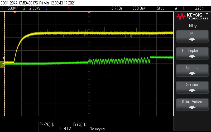
I have 4x TPS546A24A configured as single phase rail for each regulator. At the moment, there is no load device. I am pre-testing (developing FW) on the board before populating my intended load device.

All but one regulator is operating properly. The difference between this unfunctional one vs the other three functioning regulator is the output bulk capacitance.

The functioning regulators have 979uF of bulk capacitance, whereas my unfunctional regulator has only 39uF. I have tried adding more capacitance to the unfunctional regulator, and is able to regulate properly after, although this is just a hack. I anticipate my load device will have some load capacitance as well, but I don't think it will be near 940uF.

I have explored trying different gain values using the TPS546x24A_Compensation_Pinstrap_Calculator worksheet. I have not reached success yet.

My goal is to have a FW image for the regulators so that the VR can still regulate properly with or without the load device. Please advise on this issue.

  • Hi Philip

       The capacitance seems really low for the non-functional circuit. What is the designed load current of the application? As you capacitance becomes lower the LC double pole will move to higher frequency causing the circuit to become unstable. Have you tried increasing the inductance?

    When you say that the unit is non-functional, does it not startup or does it startup and shutdown due to a fault? Can you indicate what fault you are facing by checking the PMBUS status registers?

    Can you share waveforms of the non-functional unit?

    Regards,

    Gerold

  • I'm expecting the load current to be rather small about 10-100mA. 

    The inductance I am using is 3.3uH. Any suggestion for change? I have not tried higher inductance. I have built the circuit using the TI webdesigner tool.

    Just to be more complete: the design has 230uF of output ceramic cap and 39uF of electrolytic bulk cap. 

    As soon as EN is asserted, the regulator attempts to ramp-up the voltage then shuts off due to a fault. The fault is IOUT_OC_FAULT. 

    Here is the waveform for EN (yellow) vs VOUT (green):

    The pulses you see for VOUT is nearly periodic and is about 11-12kHz.

  • Hi,

    Peter is looking into this and will feedback to you soon.

    Thanks,

    Lishuang

  •  

    It appears to be a stability issue.

    What is the Output voltage?

    What is the Switching frequency and COMPENSATION_CONFIG value?  (If it is programmed by pin-strapping, if you can let me know what the MSEL1 resistor values are and I can back-calculate compensation and switching frequency) 

    Looking over the details for the pin-strapped compensation config values, getting the current loop bandwidth high enough with such a large inductor could be a problem.  The TPS546A24A wasn't optimized for 100mA load currents.

    Are you willing to try 550kHz with a 1.0uH inductor?

    The Pin Strap Compensation Code 26, which would be selected with a 26.1k resistor from MSEL1 to BP1V5 and a 31.6k resistor from MSEL1 to AGND looks like it would work with your output capacitor configuration.

    What features of the TPS546A24A are drawing you to use it for a 100mA application?

  • Hi Peter,

    I can try to set any Vout and the regulator never stabilizes. I am targeting 1.2V.
    I am using 575kHz, but I have tried down to 225kHz. No success. I suppose I can try higher frequencies.
    I uploaded a picture of my schematic. Don't mind R231, I have fixed this to 10k in an updated schematic. Also, what is not shown is 31.6uF of additional output ceramic capacitance.
    I have tried programming compensation code 26, no success there. I will work on the scope measurements for different configs.
    The reason why I went with this regulator is because I wanted to be able to control the VOUT to 400mV, if need be. Not many regulators has that much range. 
    I would be willing to try a lower inductor. But wouldn't a lower inductor make the ripple higher, and thus need more cap? I think this would make it more difficult to regulate, right?
  • I stand corrected. I tried programming code 26 again. It works!

    I must have not been using the GUI properly. I didn't "apply setting to user_data_01 and FSW" before writing to the registers.

    I have tried this over different frequencies, and so far so good. No load added yet. I suspect this will only improve the overall regulation.

  •  

    I am glad you were able to get it to work.

    It is possible you were applying the updates to the COMPENSATION_CONFIG and FREQUENCY_SWITCH commands while the TPS546A24A's output was enabled, or the COMPENSATION_CONFIG bit in PIN_DETECT_OVERRIDE was set set to 1, and the part would reload the pin-strapped compensation value with each new power-up.

    In order to protect the output from stability or large transients, switching frequency and COMPENSATION_CONFIG can not be updated while output conversion is updated.  The device will allow the command values to be updated, so they can be stored in NVM and used on future power-on resets, but the active switching frequency and Compensation remains unchanged.

    Yes, using a smaller inductor will increase the inductor ripple current and thus the output ripple voltage, but it also reduces the gain needed in the current control loop to obtain the necessary current loop bandwidth.  With such a large inductance it is difficult for the current loop to adjust the duty cycle fast enough to get good bandwidth in the current control loop.

    If you are not limited to pin-strap programming, I could recommend a PMBus programmable COMPENSATION_CONFIG that would work with a 3.3uH inductor.