This thread has been locked.

If you have a related question, please click the "Ask a related question" button in the top right corner. The newly created question will be automatically linked to this question.

TPS3128: Startup conditions for WD input

Part Number: TPS3128
Other Parts Discussed in Thread: TPS3828

Hi,

I came across a powerup issue with TPS3128E18.

Schematic:

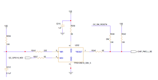
- MR#: connected to pushbutton (to assert manual HW_RESET). Currently not used, constant pullup.

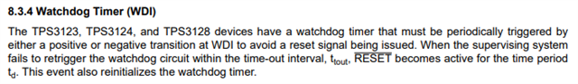
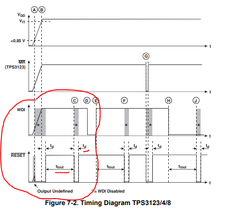
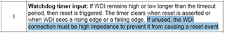
- WDI: Watchdog input from the processor.

- RESET#: connected to the processor HW_RESET input.

1V8 is clean and stable.

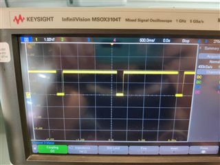
My problem is occurring on new boards arriving from manufacturing line, where WDI is at high-impedance (processor not flashed) and yet RESET# still assert reset patterns (see scope shot).

In order to verify WDI is indeed high impedance, R257 (from WDI input) was removed - component's WDI is open - and reset pattern persists.

The data sheet stated that such reset event should have been avoided.

Please advise.

Thanks,

Amit

  • Hi Amit,

    Thank you for highlighting the statement.  Because the datasheet represents multiple parts and the pin table is setup in a matrix setting, the highlighted statement is supposedly meant for the /MR pin and not for the WDI pin.  From the block diagram, you will noticed that the /MR pin has an internal pullup resistor of 27Kohms.  Also, pin #4 is the only pin in the table that represents two different pin functions.   

    Therefore, the explanation for pin4 should be,

    "Watchdog timer input:  If WDI remains high or low longer than the timeout period, then reset is triggered. The timer clears when reset is asserted or when WDI sees a rising edge or a falling edge.

    Manual Reset: Pull this pin to a logic low to assert a reset signal in the /RESET output pin. After MR pin is left floating or pulls to logic high, the /RESET output deasserts to the nominal state after the reset delay time (tD) expires."

    Just to clarify the TPS3128 WD functionality, the WDI needs to be triggered periodically to avoid a reset event.  The scope photo you provided perfectly shows that operation.  Below are some screens shots of the datasheet that explains what you saw on the oscilloscope.

    I hope I have answered your questions.

    Ben

  • Hi Ben,

    Thanks for your detailed answer.

    I understand WD functionality very well.
    I'm using TPS3128

    Please notice that my question was for it's behavior when the processor (that drives this line) wasn't flashed yet (new board) hence the trace is high impedance, or even after I removed the serial resistor R257 and the trace is "floating".

    Under these conditions at WDI input, please explain my findings - why the component keeps asserting reset?

  • Hi Amit,

    Maybe I was not being clear but the reason why your output keeps asserting is because there is a period of time where the watch dog needs an input to the WDI circuit to reset the timer.  If that period of time eclipses without a positive or negative transition, the output will assert.  See below:

    Ben

  • Hi Ben,

    Again, the statement I highlighted from the datasheet is certainly represent the WDI pin and not the MR#, as can be understood from the datasheet.

    I have large inventory of components and I want to bypass the functionality of this pin and still using the component as a voltage monitor and manual reset supervisor.

    Is it possible?

  • Hi Amit,

    As I mentioned above, the statement in the TPS3128 regarding the WDI pin being placed in a high-impedance state to prevent a reset event on the output cannot be achieve with this part. The statement is incorrect and thank you for bringing this to TI's attention.  

    If your application allows, please use the TPS3828 found in the datasheet here:

    www.ti.com/.../tps3823.pdf

    The TPS3828 will allow you to have no reset events on the output if the WDI pin is in a high impedance state.  The drawback with the TPS3828 is the voltage threshold where the part can monitor 2.5V, 3V, 3.3V, and 5V only.

    Ben