This thread has been locked.

If you have a related question, please click the "Ask a related question" button in the top right corner. The newly created question will be automatically linked to this question.

LM60440: Damage after power-up

Part Number: LM60440


Hello,

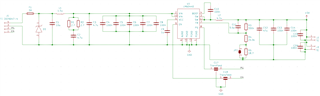
I've designed a power supply with nominal 24 V input and 5V output for a ~15 W load. I've already had 2 boards running fine for a few days at 20 W output power with 20 mV ripple.

However, despite handling them the same as the first 2 boards, I've had 6 of them fail in two different failure modes. 2 other ones ran fine for the first power-up, providing nominal output for a few minutes until I turned off the lab power supply, then the second or third time, they've got a shorted output stage. The other ones didn't give any life signs, the internal LDO only outputs about 1.2 V when EN is high.

I've already checked for any voltage transients on the input while switching the lab supply on or off, nothing. The soldering on the boards looks as good as it gets, as far as it is visible from the side, all pads are nicely wetted, and the boards where assembled and tested in an ESD-controlled environment.

Since I've made the - unwise decision to not include a pull-down resistor on the enable input, can the input floating for a short time permanently damage the IC in this manner?

Best regards

Marian

  • Hi Marian,

    Looking at the available pin FMAE for this device, it doesn't look like the device will have any permanent damage if EN is left floating. If the EN pin is left floating, it is expected that the output voltage will start to lose regulation.

    With 5Vout and 15W-20W, I'll assume worse case of full 4A loading. What is this circuit's board size? Is it a 2-layer or 4-layer board? 

    Also the inductor you selected appears too small for this application. Refer to Equation 4

    With the assume power conditions (VIN = 24V; VOUT = 5V; IOUTmax = 4A; Fsw = 400kHz (default); K = 0.3), the calculated inductor is 8.25uH. Nearest common inductor value is 8.2uH. Place change your boards to a higher inductor value and retest.

    Regards,

    Jimmy 

  • Hi Jimmy,

    thank you very much for your reply. I'm using the 1 MHz variant, so the inductance should be correct. I'm using the Bourns DR1307-4R7ML,

    The board is 4-layer with continuous ground planes on the first inner and the bottom layer. The total board size is 40 x 50 mm.

    Best regards

    Marian

  • Hi Marian,

    Thank you for the update. Yes with 1MHz variant, the inductor is now calculated to be around 3.3uH. The 4.7uH you have on your board should be correct. 

    There isn't anything particular in the schematic that I can see might result in an output short. 

    1. What is the downstream circuit the 5V rail is powering? 
    2. Is there anything downstream of the circuit that could be shorting out (damaged output caps, connector shorts, etc.) 
    3. Can you confirm if the output MLCC are at least 16V rated? MLCC quickly derate when a bias voltage is applied. 
    4. Have you tried to isolate the U1 by removing the downstream load, connecting it to a stable electronic load, and retesting functional stability/operation at 4A? 
  • Hi Marian,

    Can you provide any update on the questions I've posed previously?

    Regards,

    Jimmy 

  • Hi Jimmy,

    I only used power resistors as a test load. There are also no other shorts on the output, I measured all of them through before the first power-up. output MLCCs are also all rated for at least 25 V

    It seems like I've found the problem, I have controlled EN with a function gen while testing the boards, which allowed EN to become high at 3.3 V while the input voltage was still at 0 V. That might just be enough to reliably fry the chip, as could be expected according to the absolute maximum ratings. Still strange that this logic input has a positive clamp diode. 

    So I hope that was the issue, new boards I tested behaved fine.

    Best regards,

    Marian

  • Hi Marian,

    Yes I would suggest waiting for the input voltage supply to properly start up and stay well regulated before controlling the EN pin to enable/disable the device switching.

    I believe this might be the cause of the issues. 

    If the new boards have any more issues please let me know.

    I will close this thread for now as it seems like the issue has been resolved. 

    Regards,

    Jimmy