This thread has been locked.

If you have a related question, please click the "Ask a related question" button in the top right corner. The newly created question will be automatically linked to this question.

TLC59116: Driving Mosfets with the outputs of LED-Driver

Part Number: TLC59116

Dear TI team,

I am a SW developer, so unfortunately I'm not an expert in hardware and I hope that you can help me. I control some TLC59116 with LEDs on the outputs with an Arduino UNO. In addition, some outputs on a TLC should be used to drive MOSFET's. 

Specifically: I would like to use some outputs of the TLC59116IPWR to control each an N-channel Mosfets IRLZ44. The TLC is installed on a board that I bought, I use the ELV I2C bus LED driver order no .: 098377. ELV supplies the TLC on this board with 5 VDC. The load on each Mosfet is a power distribution board with a 16 VDC supply to which some LEDs are connected on it. The LED's are with built-in series resistors for operation at 16 VDC (model lighting).

The task of the TLC59116 is to control the gate of the mosfet with the PWM output and thus to reduce the supply voltage of the distributor board so that the brightness of the LEDs connected there can be reduced depending on the PWM value. Individual control of the LEDs is not required in this case, hence this circuit principle with the distributor board.

I would like to switch the IRLZ44 to the outputs of the TLC59116 according to Figure 3 below

http://www.mintgruen.tu-berlin.de/robotikWiki/doku.php?id=techniken:schalten

The difference between the figure 3 and my usecase is, that I want to use not the Arduino Output but an TLC59116 output to control the Mosfet Gate. I tried to make a drawing:

I would have used it now

- R1 (protective resistor between TLC output and IRLZ44 gate) with 180 ohms (I have seen the 180 Ohm in some samples)

- R2 (pulldown at the gate) with 10 kOhm (also seen in some samples)

According to ELV documents for the TLC59116 board, REXT on the TLC59116 is wired with 1 kOhm, so the output current at the outputs of the TLC is 20 mA according to the data sheet of the TLC59116.

My questions:

# is the gate resistance correct to protect the gate, or does it have to be omitted for operation on the TLC59116 outputs?

# Is the dimensioning of the two resistors correct for operation on the TLC?

# Do I need an additional pull-up resistor on the gate?
If so, why, what value and at what potential (to the TLC supply or the 16 VDC load supply). Reason for asking: In the discussion below Pullups are used, but unfortunately I don't understand the necessity:

https://e2e.ti.com/support/power-management/f/power-management-forum/334159/tlc59108-without-rext/1166540#1166540

# In your opinion, does something speak against the use of the IRLZ44 at the TLC59116? This was chosen because it has a very low Rdson and can therefore be used for my load case up to 1 A without a heat sink. In addition, it switches through cleanly at 5 VDC.

In addition here is the schematics of the TLC-Board of the ELV company I use
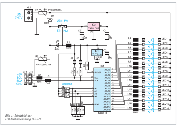
 

I apologize for my modest knowledge of electronics and also my imperfect English and hope you can help me.

Thank you in advance for your feedback!

Sincerely

Andreas Hiemer

  • Hi Andreas,

    Please see my feedback below. I reordered your questions that may better to understand.

    # Do I need an additional pull-up resistor on the gate?
    Yes the pull-up resistor is necessary. The difference between TLC59116 with Arduino GPIO is that TLC59116 do not have internal pull-high circuit. So that without pull-up resistor, the current sink block inside output pin cannot work properly.

    # is the gate resistance correct to protect the gate, or does it have to be omitted for operation on the TLC59116 outputs?
    To sink precious current, the voltage dropped on output pins need to be above saturation voltage for internal MOS, which you could refer to figure 2 in datasheet. The resistor in Arduino design is used to limit output current, since GPIO only connect the net to power supply but cannot control the current value. I do not think it is necessary for TLC59116.

    # Is the dimensioning of the two resistors correct for operation on the TLC?
    # In your opinion, does something speak against the use of the IRLZ44 at the TLC59116?
    Actually I think PMOS would be more suitable to be controlled by TLC59116, rather than NMOS. The outputs are current sinks which drive current from power supply, but not output a voltage. With an pull-up resistor, when channel on, the voltage on MOS gate would be driven to low level, which is set by the value of pull-up resistor and its pull-up level (recommend set as 0.5V for 20mA current setting). When channel off, the voltage on MOS gate is pulled high. So for PMOS, channel on drive MOS on, while channel off drive MOS off.

  • Hi Hardy,

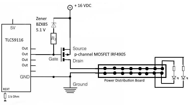
    thanks a lot for the quick response and for your interesting proposal! So if I understood right, you mean this way:


    In the TLC59116 Datasheet I found, that the max. output voltage of the TLC have to be max. 17 V.

    My 16 VDC Powersupply has a switch, to adjust output from 12 to 22 V. If this switch ist set to 22 V unintentionally, the TLC could be damaged? For this case we could use this 5.1 V Zener Diode to reduce voltage?

    Am I right with this Zener also, if TLC Out is OFF? What I'm thinking about: if there is no current, then I have no voltage drop at the diode, isn't it? Then TLC-Out Level could raise to 22 V if Power Supply is switched to this ==> Problem for TLC??
    I'd like to prevent using an additinal power regulator because of effort and power dissipation so hopefully I'm right with the idea of the Zener Diode.


    Calculation of R2: If I understood right, R2 is calculated as follows:

    16 V: Power Supply;
    0.5 V: Gate Low-Level when TLC is On;
    5.1 V: Zener-Diode
    20 mA: Current of the TLC output channel

    ==> R2 = (16V - 0.5V - 5.1V) / 0,02 A = 520 Ohm

    If I use 470 Ohm from E12, we have 470 Ohm x 0.02 V = 9.4 V at R2
    means Gate Low when TLC-Output is On is calculated to (16 - 5.1 - 9.4) = 1,5 V
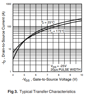
    so Voltage-Difference Ugs should be quite enough to drive the MOSFET if I'm right.


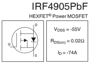
    Regarding the IRF4905: I only looked for a comparison to IRLZ44 and found the IRF4905 which has also a quite low Rdson

    If you like to suggest a TI-type, you are welcome!

    I hope, I'm right with my drawing and the calculation: It would be a great help for me, to hear from you once again. I apologize for my modest knowledge of electronics, but this project is an important one to improve my skills and hopefully, the next time I'm able to make such calculations by my own :-)


    With many thanks and all the best from Germany

    Andreas Hiemer


    Driving characteristic of the 4905 is


  • Hi Andreas,

    Yes your circuits and calculation are all right. As for MOS selection, I am also not expert for these device. You may need to start another thread. Thanks.

  • Hi Hardy,

    thank you so much for your help, really great job! I close this case with this message.

    Have a nice weekend and stay healthy!

    With all the best, Andreas