This thread has been locked.

If you have a related question, please click the "Ask a related question" button in the top right corner. The newly created question will be automatically linked to this question.

LM3549: How to set 20mA Output Current

Part Number: LM3549

Dear Sir/Ms.

My customer uses LM3549 to light up RGB LEDs, and the specifications are as follows.
Max. 500mA / per ch,
Min. 20mA/ Per ch.
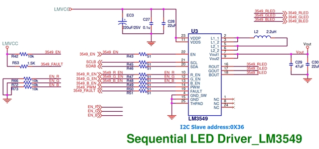
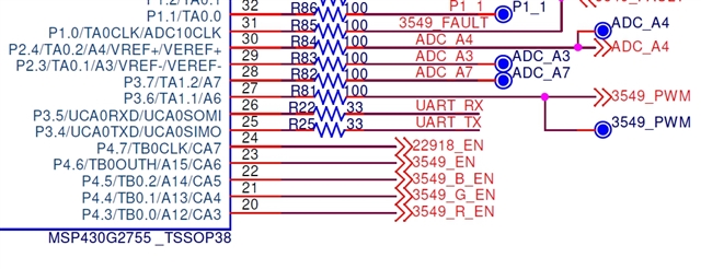
The circuit board was washed out, but found that the minimum output current can only reach 100mA. I know that this IC needs a register to set the maximum current. So I and the customer got his circuit diagram and register settings.
The schematic is as follows. If you feel that it is not clear enough, you can email to me if you need a pdf file. I can email the file to you. (my Email: kami.huang@arrowasia.com)


The register settings are as follows

Init:
para[0]= 0x00;
I2C_Master_WriteReg(LM3549_ADR,IR0_LSB, para, 1);

para[0]= 0x00;
I2C_Master_WriteReg(LM3549_ADR,IR0_MSB, para, 1);

para[0]= 0x00;
I2C_Master_WriteReg(LM3549_ADR,IG0_LSB, para, 1);
para[0]= 0x00;
I2C_Master_WriteReg(LM3549_ADR,IG0_MSB, para, 1);

para[0]= 0x00;
I2C_Master_WriteReg(LM3549_ADR,IB0_LSB, para, 1);
para[0]= 0x00;
I2C_Master_WriteReg(LM3549_ADR,IB0_MSB, para, 1);


para[0]= 0x00;
I2C_Master_WriteReg(LM3549_ADR,IR1_LSB, para, 1);
para[0]= 0x00;
I2C_Master_WriteReg(LM3549_ADR,IR1_MSB, para, 1);

para[0]= 0x00;
I2C_Master_WriteReg(LM3549_ADR,IG1_LSB, para, 1);
para[0]= 0x00;
I2C_Master_WriteReg(LM3549_ADR,IG1_MSB, para, 1);

para[0]= 0x00;
I2C_Master_WriteReg(LM3549_ADR,IB1_LSB, para, 1);
para[0]= 0x00;
I2C_Master_WriteReg(LM3549_ADR,IB1_MSB, para, 1);


para[0]= 0x00;
I2C_Master_WriteReg(LM3549_ADR,IR2_LSB, para, 1);
para[0]= 0x00;
I2C_Master_WriteReg(LM3549_ADR,IR2_MSB, para, 1);

para[0]= 0x00;
I2C_Master_WriteReg(LM3549_ADR,IG2_LSB, para, 1);
para[0]= 0x00;
I2C_Master_WriteReg(LM3549_ADR,IG2_MSB, para, 1);

para[0]= 0x00;
I2C_Master_WriteReg(LM3549_ADR,IB2_LSB, para, 1);
para[0]= 0x00;
I2C_Master_WriteReg(LM3549_ADR,IB2_MSB, para, 1);

para[0]= 0x00;
I2C_Master_WriteReg(LM3549_ADR,BANK_SEL, para, 1);

// ILIMIT 0x11
para[0]= 0x11;
I2C_Master_WriteReg(LM3549_ADR,ILIMIT, para, 1);

// FADER FFH

para[0]= 0xFF;
I2C_Master_WriteReg(LM3549_ADR,FADER, para, 1);

// MFE
para[0]= 0x0E;
I2C_Master_WriteReg(LM3549_ADR,CTRL, para, 1);

How to set the register to the customer's specification requirements. How to modify the register? At present, neither the PWM Dimming nor the register Dimming can achieve 20mA. Please provide a method that can be achieved for the customer to test.

Best Regards,

Kami Huang

  • The first line on page 4 of the datasheet.  IOUT_MIN, the Minimum output current, is about 97 to 118mA.  Figure 7 also shows that for the minimum settings of 0, the output is just a bit more than 100mA.  On page 11, under "Brightness Control" it states that the Driver currents can be adjusted from 100 mA to the maximum current set in the registers.  In other words, the registers only set the maximum current, and the minimum that can be achieved is 100mA.  Note that in Figure 18, they only show the brightness going to "MINIMUM" not "0%" when the PWM duty cycle is 0%.

  • Note that you might try using PWM on the three color enable lines to reduce the average driver current below 100mA, but there's not much supporting information in the datasheet regarding such an approach.  That would seem to not be an ideal solution for this part.

  • There is a previous topic regarding this same point in which a user states that the approach I suggested above will work.  See "LM3549: "How to get the LM3549 LED current less than 20mA ?"  (It may be in the "Similar topics" list on the side of this page.)

    If you pursue this route, the efficiency will likely be degraded when operating the device in this manner since you are switching the drivers on/off, rather than relying on the action of the variable buck-boost converter.  At the cost of added firmware complexity, one might be able to pursue a hybrid scheme where the PWM pin is used when an LED is operating above 100mA, and the when operating below 100mA, the PWM pin is held low and you control the pulse width of signal driven to the EN pin.

  • Hi Kami,

    Michael Oberling gives the proper suggestions. The register setting limits the minimum current to 100mA but by R/G/B_EN control we can configure the average output current to 20mA. 

    In addition, would you mind disclose your final customer? We have another device which is pin to pin with LM3549 and the minimum current is 20mA. But now this device is not available on the official website.

    Best Regard

    Monet Xu 

  • Hello Monet,

    Let me discuss with customer and reply you.

    Best Regards,

    Kami Huang

  • Hi Kami,

    Fine. If there is more questions, please contact me again.

    Monet Xu