Part Number: LM2775
I would like some technical support on a LM2775.
We used it in a new design but its not operating at all. (0V on output)
Our circuit:
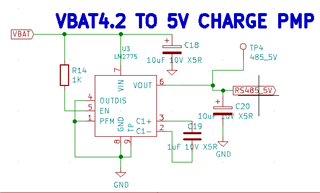
VBAT is LiPo battery (3.7-4.2V)
Vout only gives me 0V
May you advise?
This thread has been locked.
If you have a related question, please click the "Ask a related question" button in the top right corner. The newly created question will be automatically linked to this question.
Part Number: LM2775
I would like some technical support on a LM2775.
We used it in a new design but its not operating at all. (0V on output)
Our circuit:

VBAT is LiPo battery (3.7-4.2V)
Vout only gives me 0V
May you advise?
Hello 6590574,
The schematic seems to be ok, so please check if the device is setup correctly in your CAD software, check if in the layout the pins are connected as expected.
If this is all correct, please check the voltages on every pin when you apply VBAT.
Please check if the signals on the IC pins are as expected (with an oscilloscope):
VIN and EN should be high, OUTDIS and PFM should be at GND level.
Pins 2 and 3 should switch and pin 6 should then be higher than VIN.
Best regards,
Brigitte
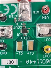
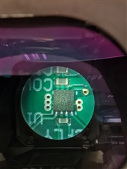
Hi can you please verify that the markings on my chip are correct?
Hi Brigitte. May you please verify the markings on my chip that it is the correct part?
Hello Gerhard,
The picture is not clear enough that I can read the marking the way that I am sure what I am reading. According to the datasheet page 20 there should be 2775 on the top side. It does not look like this.
In addition the top side looks very rough for a TI part. So I think the device you have is not a LM2775 from TI.
Best regards,
Brigitte
Hi Brigitte,
Ok so now checked and we are actually using the LM2275Q device (automotive spec) and in that case the markings match the datasheet.
So we did some measurements with scope and pin 2 and 3 has no oscillation or voltage at all.
VIN(7) -> 4.2V
VOUT((6) -> 0V
C1- -> 0V (nothing on scope)
C1+ -> 0V (nothing on scope)
(1) -> 0V(GND)
(4) -> 0V(GND)
Measuring across C19 I get DC 2V
Regards
Gerhard
Hello Gerhard,
I expect you are still speaking about LM2775Q. Then 1R1H is the right marking.
How many boards do you have that show the same behavior?
BTW, on the picture of the device I cannot finf the input and output capacitors and the flying capacitor seems to be not extremely close to the IC. In addition, there are resistors connected to pins 6 and 7 that I cannot find in the schematic. Can you please check?
Best regards,
Brigitte
It is the same on 20 boards. We checked the resistors, it is part of another part of our board, and is as it should be. Furthermore we do not believe that the capacitors are to far away from the chip. On a previous design it was further away and still worked. What can it be?
Thanks for the support!
Greetings
Burger(co-worker to Gerhard)
Hello Gerhard,
Yes, there is a evaluation board available for this device. Please check out here: https://www.ti.com/tool/LM2775EVM
For reference, here some pictures of the IC on the EVM: 

I still wonder if the top side of your devices is more rough than the ones TI normally creates. Please check as well the package you received the devices in. Where did you buy?
Best regards,
Brigitte
BTW, Burger mentioned that you have a design that works. You could try to take a unit from a working design and solder it on one of these boards to check if then the part works on the actual design.
Best regards,
Brigitte
Hi Brigitte,
Checked and double checked everything and everything looks correct.
We ordered new parts from Mauser which should arrive today. Will try and replace one and see what happens....
The only other thing that I'm unsure of is that there might be a big difference between the LM2775 and LM2775Q (accept for the ratings) ?
Hello Gerhard,
As I did not hear back from you, I expect you have been able to solve the issue and will close this thread now. If this is not the case, please post below or start a new thread if this one is locked already.
Best regards,
Brigitte
Hi Brigitte,
Sorry. It's just been hectic trying to get our production out the door.
I did find the problem. Turns out our design on you part was fine.
There was a wrong resistor placed on the line between the micro and RS485 driver chip to ground which we are powering with your voltage pump, This caused the RS485 chip to go into a mode that was causing an overload on the 5V line and your chip shutting down.
The reason why we couldn't pick it up is the overload only happens if you power both the 3.3V line and the 5V lines. During our tests we were only powering the 5V line. It is still a mystery to me why the overload because that resistor to ground is 3.3K. Unfortunately there is no time to investigate now since we need to get the production out but I will check this at a later time.
Thank you for your support
Gerhard