Hi,
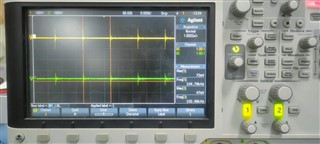
Below images are gate signal for newly assembled with supply voltage of 12V.
Confirm the signals are ok or not.
Below - Gate A & B

Below Gate C & D

Thanks & Regards,
S.Rajasekaran
This thread has been locked.
If you have a related question, please click the "Ask a related question" button in the top right corner. The newly created question will be automatically linked to this question.
Hi,
Below images are gate signal for newly assembled with supply voltage of 12V.
Confirm the signals are ok or not.
Below - Gate A & B

Below Gate C & D

Thanks & Regards,
S.Rajasekaran
Hello,
Please note that the outputs of A through F are logic level outputs and are not gate driver outputs. So if you are trying to drive FETs directly this might be your issue.
It might be in your best interest to review the evaluation module (EVM) design and waveforms; as well as, the EVM schematic. https://www.ti.com/lit/pdf/sluub02 You can also order the EVM to evaluate as well.
There is also a Webench design tool that you can use to check your design that you can find at the following link. https://www.ti.com/product/UCC28950?keyMatch=UCC28950&tisearch=search-everything&usecase=GPN#design-development
To get a better understanding of how to design with the UCC28950 it may be worth while reviewing the following design application note. https://www.ti.com/lit/pdf/slua560
Regards,