This thread has been locked.

If you have a related question, please click the "Ask a related question" button in the top right corner. The newly created question will be automatically linked to this question.

UCC5320: Case doesn't match with function table

Part Number: UCC5320
Other Parts Discussed in Thread: UCC23513, UCC23313,

Hi,

I'm facing a problem when using the UCC5320S. I want to control the MOSFET ON and OFF by GPIO7. The mosfet is driven by UCC5320S.

Bench test results:

1) When GPIO7=LOW, IN+ =10V, OUTH = 15V, OUTL=15V. (MOSFET ON). This case matches with the third combination of the function table

2) When GPIO7=HIgh, IN+ =1V, OUTH = 15V, OUTL=15V. (MOSFET still ON). This case conflictes with the first combination of the funtion table. according to the function table, OUTL should be low. Is my thought right?

Below is my schematic. Can you help to review the schemaitc, is there any wrong in the schematic?

Thank you,

Ryan

  • Hi, Ryan,

    Have you considered our UCC23513 family of devices? They are optical-input compatible, so you could eliminate your opto-coupler. Actually, I don't understand why you need it at all. Can you verify the inputs by providing a DC source driving the inputs to verify you can duplicate the truth table?

    I suspect the slow rise/fall times of the optocoupler are confusing our input structure.

  • Hi Don,

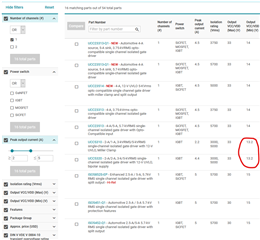
    Thanks for your reply and recommendation new part. I have a isolated 15V as the power supply for the gate driver. but 15V is unregulated, it may drop down to 14V or lower. That's why didn't select the UCC23313 at the first time. I see there is a B version which is 8V UVLO. However the UCC23313B is not presented on ti.com after parameter filter. It should be workable for my application, i will consider it in the next version design.

    Actually, I checked the UCC5320 truth table with DC source. it looks like that the first one was wrong. Could you please help me to clarify that?

    Thanks,

    Ryan

  • Hi, Ryan,

    OUTL is only a pull-down.  It can't be high by itself. You might be measuring voltage being stored in capacitance of your circuit. If you add some kind of bleed resistor, you should see this will follow the truth table in the datasheet.