


Hello,
My question is based on this discussion. Please consider the following powering scheme for the BQ76PL455A-Q1:
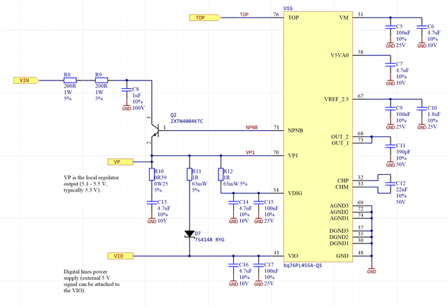
Assuming this is going to be the 1st module in string (connected to the master MCU via GPIO lines), will it be valid to attach the MCU and its 5V power to the VIO port? My logic here is that VP1 is around 5.3 V, the D7 diode will create ~0.5 - 1 V voltage drop, so the voltage at VIO (assuming no external power source connected to the VIO) should be around 4.3 - 4.8 V. Now If I attach external 5V power to the VIO, the VIO will have the 5 V level, but no reverse current will flow through the D7 to the VP1. This would also mean that the RX, TX, WAKEUP and FAULT pins would work on 5V level.
This whole exercise is to find a circuit, that would allow to use the BQ76PL455A-Q1 as a 1st module connected to the master PCB, as well as a consequent one (communicating over differential lines).
Is there any flaw in my understanding? I would appreciate all feedback.

