This thread has been locked.

If you have a related question, please click the "Ask a related question" button in the top right corner. The newly created question will be automatically linked to this question.

BQ76952EVM: The EVM has been broken down and I need possible causes.

Part Number: BQ76952EVM
Other Parts Discussed in Thread: BQ76952,

I connected the evm with a real 16s Li-ion battery. Since I wanted to charge or discharge with around 10A, I prepared CFET and DFET connected in series outside the EVM,

removing Q7, Q8 and R30 (current sensing resistor).

I put the BAT-  and  the BAT+ to J1/J3. The 16 cell monitor signals was placed in a connecter which can be directly fixed on the J23 and J14 of the evm removing the shunts for the simulator.

All went well and after I tried discharge for a few minutes, the battery had been placed in charge mode for several hours at 6.5A (limited by the capacity of current source).

There had been no problems.  When I stopped charging (charging cable is removed) and tried to plug off the connector over J23/J14 pulling out lower voltage side first (

It was not possible to lift at the same time), I heard BUM! and saw a flash. ( BAT+ and BAT- is stll attached)

After inspection I found connection point of Vss and BAT-  is broken.  The cpu is broken (Vdd - Vss has no resistance) , and BQ76952 was broken also ( TP2(BAT) showed

only 2V, giving 60V at BAT+ and no sign of REG1 REG2).

I have no idea what has been wrong. Please give me any hints that cause this situation. 

Thank you in advance,

Junkichi

  • Hi Junkichi,

    The schematic for the BQ76952EVM board is in the EVM user guide.

    Removing the sense resistor R30 would disconnect the on-board MCU ground from the IC since the MCU reference QGND is connected to PGND which is PACK-, across the sense resistor from BAT- and the BQ76952 VSS.   Communication may have been allowed through leakage paths or equipment grounds.

    Removing the FETs should not be an issue since you don't seem to have used the PACK connector J9.

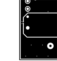
    My guess would be that while disconnecting the connectors at J23 and J14 of the board one of the cells contacted  GND such as TP14 or TP17 causing the NT1 to fuse or perhaps another trace.  A cell contacting one of the 200 ohm resistor divider pins with enough potential difference might fuse a resistor or a trace, but should be slow due to the resistance ( 60V across 200 ohm is 18W in a 0.25W resistor, other connections would be lower power) and the resistor divider references to BAT- rather than VSS. Since you mention VSS to BAT- is broken likely NT1 is open.  It is on the top layer at the board edge just below J4 and above TP9. The net ties do not have silkscreen marking, but you can see them in the layers

    You will have to decide if it is worth replacing damaged traces and any parts or starting with a new board.  I recommend leaving the sense resistor to maintain the signal references for the circuitry on board and communication interface connectors.  You can short across it if desired.  Leaving the Q8, Q9 FETs may also be acceptable, you don't have to turn them on if your evaluation does not need them.

  • Hi  WM5295,

    Thank you for the response. 

    The counterpart for R30 had been prepared outside of the board as well as CFET and DFET and all connections had been made to be topologically same with the original board. So there should not have been an communication problem. Sorry for the poor explanation.

    I am almost convinced, as you suggested, some cell voltage had a contact with a certain lower voltage part, but my problem is that so far I could not find any trace, and that makes me a bit nervous.

    Now my question is: 

    Is the device in no way damaged by disconnecting any cell voltages other than BAT- and BAT+ , even for example during cell balancing?

    Or is there a preferable procedure before removing cell monitoring voltage points?

    Thanks again,

    Junkichi

  • Hi Junkichi,

    For the BQ76952 the VC1 to VC16 inputs can be any voltage between BAT- and BAT+ as long as they are not reversed (you can't have VC10 at cell 10 voltage and VC11 at cell 9 voltage for example).  Normally a connector won't allow that.  Connection to the wrong voltage as long as cells are not reversed is OK, for example if cell 9 contacts some other cell input with others not connected it is OK.  VC0 is limited in range, but that is connected to BAT- on the board.

    No special procedure is needed to disconnect.