Other Parts Discussed in Thread: UCC21521CEVM-286, UCC21530EVM-286,
1. Is DT pin able to left open? Or is it better to connect to VCC or GND if it's no used. is RDT or CDT necessary?
If it can not left open, what's the reason?
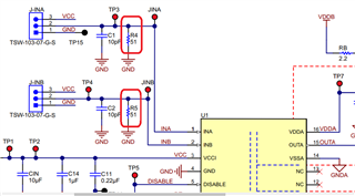
2. How to design the RIN resistor value for INx? Is this RIN resistor able to affect the sinking/souring current of the output x rail?
3. How to well design the RON resistor value?
4. In the application circuitry of the d/s, there is a zener diode of the 5.1V. what's this purpose? Is it necessary?