This thread has been locked.

If you have a related question, please click the "Ask a related question" button in the top right corner. The newly created question will be automatically linked to this question.

LM5122: Inquiry

Part Number: LM5122

Hi,

Good day.

Our customer is using the LM5122 and they are facing some issue. Kindly see the info below.

"I have some questions about the working of the LM5122 IC
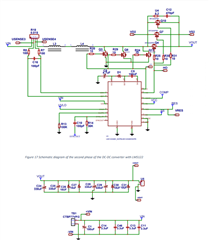
We created a DC-DC converter of 4.5V/50A to 24V
However it seems that too much current is required which causes the power supply to shut off

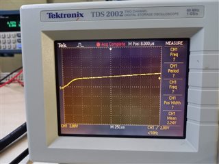
So the problem is that when I turn on the power supply the system will immediately turn off
* The schematic doesn't show any Css however this one was later added 100nF
Also only two of the three mosfets that are drawn are actually connected
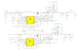
I also have a image of the simulation where this design is based on but not the actual simulation files


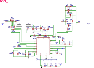
Thank you for your help.


Regards,

Cedrick

  • Hi Cedrick,

    What kind of turn-off did they see? Was the controller not switching? Or the SS pulled down? Or VCC dropped?

    And what are the two waveforms attached?

    Thanks,

    Yinsong

  • Hello Yinsong,

    Thank you for your response.

    Kindly see below the feedback:

    "What kind of turn-off did they see? : Power source would shut off automatically when the working voltage of the LM5122 was reached (4.5V). The coils on the PCB would then slowly discharge.

    Was the controller not switching? The Lo was providing a PWM signal shown in the 20210413_122417.jpg. However, the Ho was not providing a PWM signal which was expected shown in 20210408_103631.jpg.

    SS was connected with an 82uF capacitor to ground but does have a charge. When the Css is not connected this is the Lo (20210408_103827.jpg) signal.
    VCC drops when the source shuts off.

    The waveforms are Lo (20210413_122417.jpg) and Ho (20210408_103631.jpg) for both ICs the same waveform was generated.

    Lo:


    Ho:


    Regards,

    Cedrick

  • Hi Cedrick,

    Thank you for the information. When you say "power source", are you talking about the VIN in the schematic?

    If the LO is still switching, the output voltage could still be charged through the body diode of the high side FET. What is the output voltage in that case?

    Thanks,

    Yinsong

  • Hi Yinsong,

    Good day.

    "When you say "power source", are you talking about the VIN in the schematic?
    --Sorry for being unclear, correct that is what I meant.

    If the LO is still switching, the output voltage could still be charged through the body diode of the high side FET. What is the output voltage in that case?"
    --The output voltage is slightly below the input voltage (Vin). When Vin is about 3V it measures at about 2.3V.


    Regards,

    Cedrick

  • Hi Cedrick,

    Thank you for the information. The minimum voltage is 4.5V for startup so it is normal to have 3V input and 2.3V output as LM5122 is in shutdown mode. If they are having issue with the power source, please first make sure the current limit of the power source is enough and try starting up with no load.

    Thanks,

    Yinsong

  • Hi Yinsong,

    Just got a feedback from our customer.

    "I did the test and was able to get the 24V on the output.
    However, the moment I connect a load it shuts off again.
    It also happens when trying to connect a multimeter.

    I set the input voltage to 5V and current to 5A.
    I also tried it with 5V and 20A but there was not difference.
    The power source shouldn't have a current limit or voltage limit active but I don't know if it has any other safety feature."

    Regards,

    Cedrick

  • Hi Cedrick,

    Thank you for the information. There is a quick way to make sure the power supply is set correctly. Since the power supply needs to source about 50A current, please try connecting the 50A load to the power supply directly and see if the power supply can hold.

    It also helps to use a constant current load and increase the current from zero slowly and see when it shuts off.

    Thanks,

    Yinsong

  • Hi Yinsong,

    Thank you for this procedure to test the supply.

    I've got a feedback from the customer and here's what they said:

    ""I did some tests today.
    It did indeed seem to be a problem with the power supply.
    The power supply can also be used as load and there was a extra setting that prevents the supply from providing power.
    So now it is able to power a load.

    However, when I connect it with a input of 5V/5A to a load of 100ohm the MOSFETs heat up to extremly high temperatures.
    The output is also only able to get to 3.3V and 1A.
    I am not sure what I should try like should I increase the input current because the system isn't able to get the 24V which causes it to attempt to incease the PWM signal which causes a high resistance within the MOSFETs or is there something else I am missing?
    ""

    Can you please help us further? Thank you.


    Regards,

    Cedrick

  • Hi Cedrick,

    Could you help confirm their operating condition? If the load is 100ohm how could it get to 3.3V and 1A? Or are those two different cases? If so, what is the output voltage of 100ohm load? And what is the output voltage if no load?

    Thanks,

    Yinsong

  • Hi Yinsong,

    Here's the feedback of our customer:

    Could you help confirm their operating condition? If the load is 100ohm how could it get to 3.3V and 1A?

    That is what I don't know I think most of the energy is wasted over the MOSFETs seeing that they heat up a lot.

    If so, what is the output voltage of 100ohm load?

    The output with no load is the expected 24V.


    I might be able to increase the load to be higher and slowly go down to decrease the stress on the system?
    Or maybe the load was set incorrectly later with the same load It was set to Constant Resistance but changed to Constant Current so It might have tried to get a constant current of 1A which might have caused the problem?


    Regards,

    Cedrick


  • Hi Cedrick,

    It shouldn't be if the 3.3V and 1A are referring to the output voltage and output current, respectively. So please confirm with the customer. The concern is that if there is some additional leakage current unknown. Usually, the electronic load will display its mode so if it change from CR to CC it will show. If not, they can also try using a real resistor instead of a electronic load and make sure that the resistor can handle the power expected.

    Thanks,

    Yinsong

  • Hi Yinsong,

    Thank you for your inputs.

    Just got another feedback from the customer, it seems it is now working and they have another question. Thank you for your patience.

    Kindly see below their feedback.

    ""I think every thing seems to be working now.
    Thank you for all the help and sorry for the dumb questions.
    Just slightly new to this kind of testing with unkown hardware it is difficult to debug what all the possible problems could be.

    This said it does seem to function as expected, however, the temperature does seem to increase of the MOSFETs at 6v/11A input. But only at one of the phases.
    Temperature increase to about 50 degrees celsius.

    Not sure what the problem can be measuring the voltage over the shunts seem to give the same voltage measurement.
    However, the voltage might not be accurate enough.
    ""


    Regards,

    Cedrick

  • Hi Cedrick,

    Thank you for the update. Besides measuring the CSP-CSN differential voltage directly, they can also measure the current of the inductors and compare the duty cycle of the two phases.

    Thanks,

    Yinsong