This thread has been locked.

If you have a related question, please click the "Ask a related question" button in the top right corner. The newly created question will be automatically linked to this question.

TPS25980: Possibility to change Ilim value in any moment

Hi team,

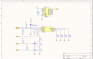
I'm designing a system board for 20-30 power switched channels. Every channel will switch and guard it's load with a TPS259807 chip. The monitoring system will know the E-fuse tripped by reading PG signal while EN is on. It's required to set the I-lim pin to control the channel current limit. I plan to do this by means of a group of switches This switches will be made with P-channel Mosfet transistors and resistors, but my doubt is if this switching can be done in any operating state (Vin present, switch on, with or without load, or switch off) without problem, or if this parameter must be changed only in an specific state of the TPS259807 to avoid malfunction instability or erratic operation The System will operate at Vin 12-24V The inputs CTL0 and CTL1 will swing from 0 to 3.3V The schematic of the switch is attached in png If this E-fuse is not appropriate for this system please refer to a replacement part that can operate in the said condition.

Thanks

Best regards,

  • Hi Zhonghui,

    Thanks for reaching out. I will get back to you by monday.

    Regards

    Kunal Goel

  • Hi Zhongui,

    I see no issue in dynamic current limiting . But I will recommend to test it ,you can test it on  EVM. For curiosity I wanted to know why is there requirement of different current limits on same channel?

    Regards

    Kunal Goel

  • Hi Kunal,

    Thank you for your reply.

    My client asked me to change the current limit of the switch, because he will use it for a switch board which will power different modules, and hence he needs different limit currents.
    This board will use 18-20 switches each, and the output will go to a terminal block. I'm attaching the layout that I'm using for you to check if you can object something in it.
    It is realized in four layers, going by the layout guidelines of the TPS259807 datasheet.
    The circuit, appart of the I lim selection, its the same as the one on the datasheets. The red traces are top signal layer, light blue Mid2 (carrying Vin) the toast traces are Mid1 (carrying GND) Blue traces are bottom signal layer. Decoupling Cap C15 is on bottom. All the parts are 0402 size.


    Best regards

  • Hi Zhonghui,

    Layout looks fine. It looks you have followed layout guidelines in datasheet which is good. Also have you created at a signal ground island and then connected it to power GND at some point?

    Regards

    Kunal Goel

  • Hi Kunal,

    Thank you for your commitment!
    I indeed have a question about the Ilim pin voltage. I've seen that the Ilim parameter is set by a resistor ratio, but as I have no availability of a EVM kit for the TPS couldn't measure that voltage.
    I think the internal circuitry for Ilim is somewhat similar to the one for the Imon pin but can't tell the Ilim voltage over the proposed resistors for certain.
    Can you tell me how to calculate the voltage on the Ilim pins for different resistors and output currents?

    Best regards,

  • Hi Zhonghui,

    Current at ILIM pin is scaled down version of current through device. You can calculate voltage at ILIM pin as GIMON*IOUT*RILIM. GIMON is mentioned in datasheet EC table.

    Regards

    Kunal Goel

  • Hi Zhonghui,

    Closing thread for now. If any issue comes up related to this thread please feel free to post here.

    Regards

    Kunal Goel