This thread has been locked.

If you have a related question, please click the "Ask a related question" button in the top right corner. The newly created question will be automatically linked to this question.

BQ25883: BAT output vs. PACK input

Part Number: BQ25883
Other Parts Discussed in Thread: BQ28Z610-R1, BQ28Z610

Hello,

My circuit uses the BQ25883 for Charger, and the BQ28Z610-R1 for Gauge. This is my circuit:

On the BQ25883, I have "Enable Charge" and the "Charge Voltage" set to 9.2V. Here's an image of the configuration:

Now, when I plug the USB cable to my board to charge the battery (thus providing 5V to the VBUS pin of the BQ25883), this is what happens at the BAT pin of the BQ25883 that's connected to the PACK pin of the BQ28Z610-R1:

And like this, the batteries won't charge.

If I detach the BAT pin of the BQ25883 from the PACK pin of the BQ28Z610-R1, I get this at the BAT pin:

This next image shows the BQ28Z610-R1 status:

Is there anything wrong with this circuit / configuration?

Thanks,

Ed

  • Ed,

    If I detach the BAT pin of the BQ25883 from the PACK pin of the BQ28Z610-R1, I get this at the BAT pin:

    This scope capture is the expected behavior for the no battery condition. Please refer to Figure 76 in the BQ25883 datasheet

    My circuit uses the BQ25883 for Charger, and the BQ28Z610-R1 for Gauge. This is my circuit:

    The BQ schematic looks good and has obvious no errors.

    Now, when I plug the USB cable to my board to charge the battery (thus providing 5V to the VBUS pin of the BQ25883), this is what happens at the BAT pin of the BQ25883 that's connected to the PACK pin of the BQ28Z610-R1:

    I am unsure about this waveform . What is the VBATT+ voltage as well as CHG and DSG?

    Is there anything wrong with this circuit / configuration?

    can you comment on the gauge registers and schematic?

    Best Regards,

    Ricardo

  • Hello Ricardo,

    The signal at VBATT+ (the BAT output of the BQ25883; pins 13 & 14) is this:

    Its changing between 7.2V and 8.6V every 350ms (2.857Hz).

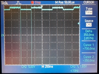
    The signal at CHG (pin 9 of the BQ28Z610-R1) is this:

    Its changing between 16.8V and 18.2V every 350ms (2.857Hz). Its being measured from GND to CHG. I tried measuring from GND2 (the BQ28Z610's ground) and CHG, and got the same values. Not sure how it's achieving these voltage values.

    The signal at DSG (pin 7 of the BQ28Z610-R1) is this:

    Its changing between 16.8V and 18.2V every 350ms (2.857Hz). Its being measured from GND to CHG. It's almost the same as the CHG pin except for a small phase shift.

    The current batteries voltage is 7.47V (measuring from the 2 batteries in series).

    Best regards,

    Ed

    PS (1): The board was plugged on a USB charger for the images above.

    PS (2): If I bypass the gauge circuit and connect the BAT output of the BQ25883 (pins 13 and 14) directly to the batteries, completely disconnected from the BQ28Z610 circuit (batteries on a separate battery holder outside the board), the batteries will charge perfectly using only the BQ25883 circuit of the board. So the problem appears to be on the BQ28Z610 area.

  • Seeing that if I connect the BAT output of the BQ25883 (pins 13 and 14) directly to the batteries, completely disconnected from the BQ28Z610 circuit, the batteries will charge perfectly using only the BQ25883 circuit of the board, is it possible that a simple setting on the BQ28Z610 be preventing the batteries to charge?

    I went through all settings of the BQ28Z610 and they all seem right to me. But I might be missing something.

  • Hello Eduardo,

    Can you enable the lifetime tracking and run the test with the gauge? The bq28z610 has logging features that will show if a failure or safety has been triggered. You may be triggering a protection then clearing it multiple times. Are you able to confirm the CHG and DSG pins are toggling on the gauge to confirm it is the gauge?

    Sincerely,

    Wyatt Keller

  • Hello Wyatt,

    About the CHG and DSG pins:

    If I don't connect the USB cable to the Charger IC (the BQ25883), both the CHG and the DSG pins of the BQ28Z610-R1 (pins 9 and 7) stay steady at 17.5V.

    If I connect the USB cable to the Charger IC, I get the waveforms shown on the images above on the CHG and DSG pins, which are those:

    About the lifetime tracking: 

    I have enabled it by setting ManufacturingStatus[LF_EN] = 1. However, as far as I understand, it can only log:

    - Max Cell Voltage for Each Cell

    - Max Charge/Discharge Current

    - Max/Min Cell Temperature

    One interesting thing though: When I looked at the Data Graph, I added "Cell 1 Voltage" as well, and this is what happened:

    The left side of the graph was before I plugged the USB cable to charge the battery. The right side of the graph was after I plugged the USB cable.

    Questions:

    1) Does the CHG/DSG graphs above (oscilloscope images) looks correct? Seems to me that they should not reach 17.5V, and that they should touch 0V when dropping. I don't even understand how they are reaching 17.5V.

    2) When you said "enable the lifetime tracking and run the test with the gauge", what test were you referring to? Was it to attempt to charge the batteries?

    Best regards,

    Ed

  • Hello Ed,

    I don't believe it is the gauge that is turning the charge on and off, the gate voltage should drop down to 0V when it's disabled if your testing with a similar schematic as the EVM. The lifetime data will let us see if anything is out of bounds that is expected, it looks okay to me.

    Is the charger switching during the on period and off during the low period of the cycles? It looks like the gauge is leaving the FETs open and the CHG and DSG pins are just changing as the charge voltage does and not completely shutting off.

    Sincerely,

    Wyatt Keller

  • Hello Wyatt,

    Well, I removed D1, Q3 and R11 (the FET responsible for preventing reverse battery polarity on the schematics I included on the 1st post), and then it started working. Not sure if it was something wrong with my design, with solder or with the FET itself, but that solved the issue. But I reviewed that part several times and it looks right. Do you see that FET preventing charging?

    Best regards,

    Ed

  • Hello Eduardo,

    I'm not sure why it would prevent charge, Using a circuit simulator like TI Tina may help identify if it's the schematic or a faulty part issue.

    Sincerely,

    Wyatt Keller