This thread has been locked.

If you have a related question, please click the "Ask a related question" button in the top right corner. The newly created question will be automatically linked to this question.

[FAQ] : What is the difference between LM74700-Q1, LM7480-Q1 and LM7481-Q1?

Part Number: LM7480-Q1
Other Parts Discussed in Thread: LM74800-Q1, LM74700-Q1, , LM7481-Q1

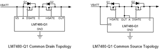
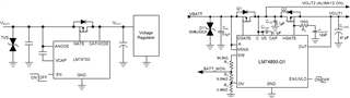
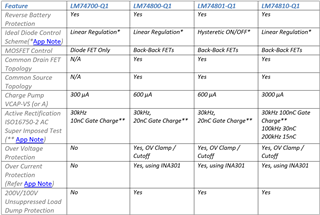
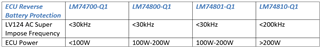
What is the basic difference between Ideal Diode Controllers LM74700-Q1, LM74800-Q1, LM74801-Q1 and LM74810-Q1?

RELATED PRODUCTS: LM74700-Q1, LM74800-Q1, LM74801-Q1 and LM74810-Q1

  • Background:
    LM74700-Q1 is an Ideal Diode Controller driving an N-Channel MOSFET to emulate an ideal diode in reverse battery protection, reverse current blocking and ORing applications. When the controller turns off the MOSFET, body diode conducts current in the forward path, i.e., power path is not cut-off.

    In many applications it is required cut-off the power path during over voltage conditions or lower power sleep mode. Second MOSFET is required along with the “Ideal Diode” MOSFET connected back-back to provide over voltage protection or load disconnect during shutdown. As discussed in FAQ 5, LM74700-Q1 is not suitable to drive two back-back connected MOSFETs.

    LM7480-Q1 and LM7481-Q1 family of Ideal Diode controllers feature industry’s first dual gate drive to control back-back N-Channel MOSFETs, one MOSFET to emulate an ideal diode in the same way as LM74700-Q1 and other MOSFET for load disconnect, over voltage protection including unsuppressed load dump protection. Further, both LM7480-Q1 and LM7481-Q1 support universal control topology - common-source topology and common drain topology.

    Simplified diagram of common-drain (CD) topology and common-source topology is shown in Figure 1. Common Drain Topology is preferred for applications where “Always ON” circuits are required to operate. CAN/LIN communication MCU are mostly required to be always ON in low power state. Common source topology is required to support 200V/100V unsuppressed load dump.

    Figure 1: Simplified Diagram: LM74700-Q1 CD and CS Topology

    Comparison:
    Typical application circuits of LM74700-Q1 and LM74800-Q1 in CD topology are shown in Figure 2. 

    Figure 2: Typical Application LM74700-Q1 vs LM74800-Q1 in CD Topology

    Next, Table 1 provides a detailed comparison of feature and performance comparison of all the four controllers.

    Table 1: Comparison of Ideal Diode Controllers

    LM7480-Q1 and LM7481-Q1 feature increased charge pump capacity to drive large MOSFETs with higher gate capacitance than LM74700-Q1. For higher power applications, LM74810-Q1 is recommended. Table 2 highlights the recommended devices based the ECU power requirements.

    Table 2: Device Selection based on ECU Power Requirements

    References: