This thread has been locked.

If you have a related question, please click the "Ask a related question" button in the top right corner. The newly created question will be automatically linked to this question.

TPS61236P: The output is shorted to ground but there is current flowing between the output and ground and the current increases until is passes 1A

Part Number: TPS61236P

Hi Team,

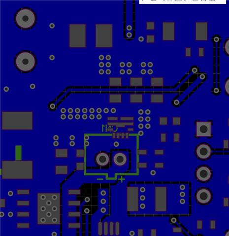
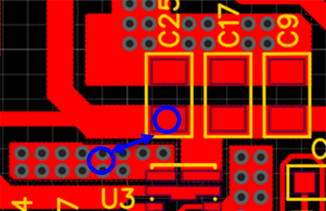
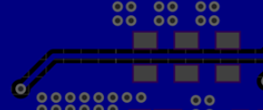
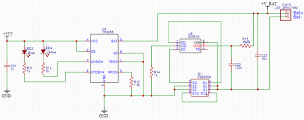
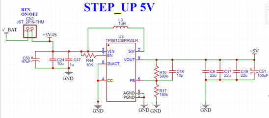
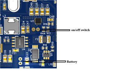
Our customer noticed that when he shorted the output of TPS61236P to ground there is a current flowing between the output and ground and the current increases until is passes 1A. Attached are the schematic diagram and PCB layout for reference. The output of CN10 is connected to a lithium-ion battery which is connected to pin 2 of CN1. The CN1 is an ON/OFF switch to disconnect the battery from the TPS61236P boost converter. C50 and C49 are not installed in the board. 

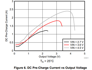
I understand that the ILIM_pre is up to 0.8A (max) if the output is 0V, why does the current exceeds 1A?

Regards,

Danilo

  • Hi Danilo,

    Do you know how does customer short Vout to GND. If they use long cable to short Vout to ground, TPS61236P may see Vout voltage > 1V because of long cable resistance. Please let customer use multimeter to measure Vout pin voltage again.

    Could you share the layout, not 3D board picture? One thing is clear that customer didn't put the output capacitors close to IC.

  • Hi Zack,

    Thank you for your response. According to the customer he used small/short wires/cables and also tweezers to short Vout to ground. He measured the Vout pin voltage while it is shorted to PGND, the value is 0.1V(output pins) or 0.075V( in the capacitor terminals). Please see the PCB layout below.

    Regards,

    Danilo

  • Hi Danilo,

    We will check it on EVM.

    Could you let customer measure Vout pin, Iin current waveform and share with us?

    Meanwhile, I see the layout is not perfect. The output capacitors(C25, C17, C9) should be put as close as possible to IC Vout pin and GND pin so that the switching loop is minimum.

  • Hi Danilo,

    I have tested it on EVM and don't seem to find this problem.

    First, IC is open load and then I use tweezer and power cord to short the output capacitor (C6) on EVM. Iin (Iout) changes to 0.256A while Vout is 18.3mV. The waveform is shown below.

    Could you let customer directly short output capacitor and measure Vout and Iin waveform? Maybe test method or PCB layout cause customer's problem.

  • Hi Eric,

    Here are the waveforms at different test conditons. 

    T1 - Measurement of the two channels during the short-circuit at the output.
    CH1 (Yellow) Vout
    CH2 (Purple) Vin (battery)

    T2 - Measuring the short-circuit only at the output (Vout)

    T3 - Measurement of the output voltage Ripple without load.


    T4 - Voltage ripple measurement at the output(Vout) with 10R load

    Note: In some moments of the short-circuit test the current was around 750mA.

    Regards,

    Danilo

  • Hi Danilo,

    The short-circuit Vout in T2 seems to be about 0.5V, so the max ILIM_pre will be higher. I didn't find such problem when short-circuit Vout is 18.3mV. You can let customer try to short the Vout pin directly to test. Customer didn't put the output capacitors close to IC may cause tested Vout is higher than 0.

    Best Regards,

    Eric Yue

  • Hi Eric,

    I just received a feedback from the customer as follows.

    I did new tests on the pcb. First I removed the resettable fuse (PTC), then I short-circuited several Vout points (IC output) with tweezers and a short cable. In all cases the voltage at the output of the IC was 0.2 Volts and the current started with a value of 0.62 A and increased as the short circuit was maintained.

    I read your answer about the output capacitors, I would like to be sure if the problem is their distance from the IC. The pcbs are made in another country, so there is a delay of a few months until I receive them with a new correction.

    Could you help me in any other way? I would need more certainty to correct this design of this pcb. Do you have any idea on what, in addition to the capacitors, could be causing this?

    Regards,

    Danilo

  • Hi Danilo,

    Sorry, where is PTC and its effect on short Vout? I did not see it in PCB. and how did customer short Vout, through Cout or directly short IC Vout pin?

    Maybe can short C17 or C25, or even directly short C25/C17 Vout pin and GND vias, which is shown below, to compare and measure Vout and Iin waveforms. Since length of PCB output loop is uncertain, so the problem cannot be certain determined.


    Though PCB review, the output loop seems long because Cout is not close to IC and GND will also detour in bottom layer. Even by shorting C25/C17, Vout still has a long loop. I think it's main cause because the problem happened on output. Maybe FB resistors can try to changed larger value, but I think the key issue is short Vout and GND near IC through a short loop to see whether problem is fixed.

    Best Regards,

    Eric Yue