This thread has been locked.

If you have a related question, please click the "Ask a related question" button in the top right corner. The newly created question will be automatically linked to this question.

SM72295: HOB Turn on issues with SM72295

Part Number: SM72295

Hello,

I am using the SM72295 in my Charge Controller design and I am having issues getting the HOB line to turn on as I want.

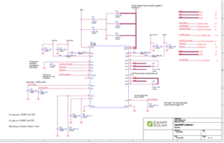
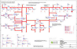
Using the signal OUTPUT_FET_DRIVE I am attempting to turn on/Off HOB and get 2 output MOSFETs (Q5 and Q6) to turn on. I want to turn them on above a certain charge current and turn them on below that current. Currently, I can charge at up to 20A successfully by driving the PWM_HIA and PWM_LIA signals. However, toggling the OUTPUT_FET_DRIVE does nothing to the HOB signal and thus Q5 and Q6 stay off constantly resulting in loss during buck conversion. No matter what OUTPUT_FET_DRIVE does, HOB stays at the same potential as HSB.

Any idea what could be happening here? 

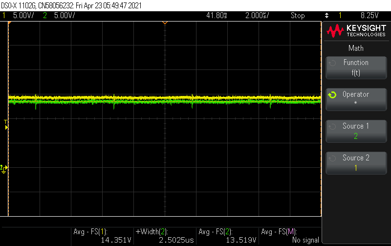
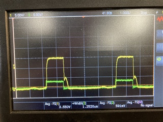
Below I have images of my schematics and below those I have various images of the device signals labeled when the device is running with a 40Vmp panel at ~315W

Yellow (ch1) = BRIDGE_FET_G1 / Green (Ch2) = HSA

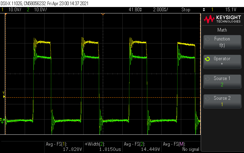
Yellow (ch1) = BRIDGE_FET_G3 / Green (Ch2) = HSA

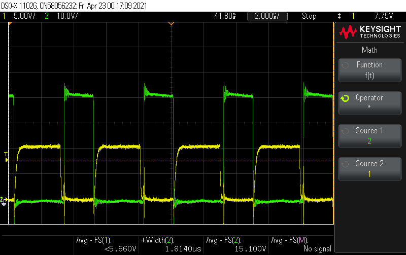
Yellow (ch1) = HSB / Green (Ch2) = Battery Output (Note, BRIDGE_FET_G2 is the exact same voltage as HSB and does not change in response to driving OUTPUT_FET_DRIVE to 3V)

  • Hello,

    Thanks for reaching out.

    We're reviewing your application details, we will get back to you promptly.

    Regards,

    -Mamadou

  • Hello, 

    I assume from the issue description that is consistent on HIB and HOB only, please confirm.

    In order to accurately diagnose possible root cause, I have questions to understand the issue at hand.

    It looks like you're using the IC to drive parallel FETs on both high and low-side gates and that HOB is stuck high regardless of the HIB signal level, can you also confirm?

    Does this issue occur at some point during steady state after initially working? or consistently at startup?

    Meanwhile, from your schematic, I suggest adding a third decoupling cap on VDD >=4.7uF because of the high gate charge, the driver will require sufficient charging current from VDD caps to replenish HB_HS capacitors.

     Thanks.

    -Mamadou

  • Hello,

    Thank you for your response.

    Your assumption is correct. I only ever have an issue with HIB/HOB.

    Your understanding is correct except that HOB is stuck low. Any time I sample the HOB gate at the gate of the MOSFETs (Q5 and Q6) the signal is identical to HSB. Thus, these MOSFETs never turn on and the current is running only through the body diodes. I tried to demonstrate this by showing that HSB is constantly 0.7v-1.0V above the battery any time charging is occurring. This behavior is causing excess power loss which is manifesting itself as heat loss and inefficiency.

    I only try to turn on HOB after a steady state has been working. My goal is to turn on HOB at charge currents over 10A and leave it off under this but currently I am unable to turn it on at any current value.

    I am not able to turn on HOB in any condition it appears. I have a separate operating mode used to calibrate the device. In this mode, I put 25V on the solar input and a resistive load on the output. I then attempt to turn HOA and HOB on by driving the two signals high. HOA turns on successfully (>6V Vgs) but HOB does not (Vgs <0.3V). I have done this test with about 25V and 5A and also at around 2A with the same results. Just to reiterate, in this mode, LIA is completely off. 

    I will attempt to increase the capacitance on VDD and see if this helps the functionality. 

    I have a few questions.

    1. Could this also be a result of the 10V Buck I have on the device not sourcing enough current? 

    2. If this is related to current sourcing, shouldn't the device be able to operate properly at lower charge currents where the demands on VDD are lower? If HOA is taking so much current, why would I be able to drive LOA whenever I want while HOA is operating but not be able to use HOB while HOA is active and LOA is off? 

    3. What should the waveforms on HBB and HSB (across capacitor C46 in my schematic) look like to ensure that this capacitor is getting adequately charged?

    Thanks,

    Austin

  • One more thing. You mention VDD capacitance. This is the 3.3V rail I have. Based on the block diagram on page 6 of the SM72295 datasheet, it looks like VCC is charging HBB. Could you please confirm that you meant to add more capacitance to VDD and not VCC? 

  • Hello Austin, 

    For the interest of debugging, with a new unit, let us disconnect the bus voltages (if you have tried this already, please let me know) Vin_conv and Vout_Conv and just drive the input side with the same PWM signals to confirm whether HOB goes high. In this condition, the IC is simply driving the gates 25V disable. This allows me to understand whether the issue is related to the power stage or whether from the driver IC itself. 

    If in those conditions, no HOB output still, let us remove gate components to have the IC in stand alone disconnect from the gate to check the output goes high. This should provide answer to your first question if I understand it correctly.

    2. This question actually reminded to check where the decoupling capacitors are located with respect to VCCA and VCCB since they both share the same supply and caps on the schematic. Ideally, you'd want each decoupling pin with its own local decoupling caps to effectively source/sink current to the gate.

    Each VCCA and VCCB should have its own caps 0.1uF and >=4.7uF such that VCCx caps >=10x HB_HS caps.

    3. C46 should be >=6.6V (HB-HS threshold to ensure that HOB is saturating to the gate drive voltage. Please review the attached app note discussing charging and sizing C46.

    Please let us know if no improvements once you have updated the caps above.

    www.ti.com/.../slua887.pdf

    Regards,

    -Mamadou

  • Mamadou,

    Thank you for your help on this. 

    I conducted the test you recommended. I removed the current sense resistors thus removing voltage from VIN_CONV and VOUT_CONV.

    When I drove HIB in this scenario I was able to observe the gate driver working properly as shown in the scope capture below. Green = HIB and Yellow = HOB. Could you maybe shed some light on what that second hump in the HOB signal is during the falling edge? I have seen this sometimes on my LOA signal as well.

    I have run further tests as well on boards with a normal configuration (VIN_CONV and VOUT_CONV connected). 

    I added 4.7uF of capacitance to VCC across pins 21 and 23. I then attempted to turn on HOB as before. I observed the same results (i.e. The gate driver was unable to drive HOB). When I measured the voltage from HBB-HSB I observed that HBB was actually below HSB by above 0.4V. I observed HSB at 15V and HBB at 14.6V.

    My understanding of this is that it is most likely my 10V power supply (VCC) that is unable to source enough current to drive both sides of the gate driver high simultaneously. Either that or the bootstrap capacitance needs to be greatly increased. However, based on the app note you sent me, I have more than enough bootstrap capacitance to have the device function like it should. 

    I am going to attempt to remove the 10V buck converter and instead inject a 10V power supply to see if this improves things.

    -Austin

  • Mamadou,

    I removed the 10V supply from the circuit and drove this circuit using a power supply. I got the same results. When HOA is operating and HIB is driven, the voltage across HBB and HSB drops to negative. (HBB = 14.2V, HSB = 14.7V). Without attempting to drive HIB, the voltages are HBB = 15.8V and HSB = 14.7V.

    This was done on the same board that has 4.7uF in extra capacitance on the VCC line right near the SM72295.

    Thanks,

    Austin

  • Hello Austin,

    Thanks for the additional information.

    HBB should always have higher potential for HOB and above the HBR threshold 6V with respect to HBS for the high side channel to be active.

    I assume the latest measurements are taken with a new IC, I want to make sure that the driver is not already damaged as we debug. We recommend at least 10x though in reality you may size the caps to much higher than that to allow for sufficient margin. We also want to make sure that the VCC supply can sufficiently charge up both the HBB and HBA capacitors above the UVLO threshold so that HOA and HOB output can drive the gates.

    The hump appears to occur after the HIB has transitioned to low state which seems to occur during the falling edge only. It is unclear whether this is coming from the transistor as it is ~Miller region. Few ohms resistance on the falling edge might help smooth this. We can check this by removing the anti parallel diode and establishing a single path for both turn-on and off.

    The latest results appears to indicate that the HBB is not charging up to the UVLO threshold. During these measurements, what is the voltage directly on VCC lines? I suspect that the VCC is at 10V otherwise HOA would also be stuck to GND since both VCCA and VCCB are shorted.

    Can you confirm that both VCCA and VCCB have their local capacitors directly on the pins? In other words, both are sharing the C36, C38 and C40 whereas each one should typically have their own >=4.7uF local decoupling capacitors close to the supply pins given the high gate charge FETs and HB_HS capacitance.

    Regards,

    -Mamadou

  • Mamadou,

    Yes these latest measurements were done on a new IC.

    I think I have a new understanding of what is going on. I will start by detailing how I understand the HOA/LOA drivers to be operating properly.

    When LOA is turned on, HOA is off. This allows HSA to be pulled to ground. When HSA is grounded, the capacitor across HBA and HSA is charged up through the diode from VCCA to ~10V. When the gates switch (HOA is on with LOA off) the 10V potential remains across the capacitor and allows the HOA driver to drive HOA with the potential built up on HBA.

    I think the reason that HOB is not working is that HSB is never driven to ground. For correct operation, I would need a low side mosfet on LOB that would drive HSB to ground just as is done with the HOA/LOA combination so that the capacitor across HBB-HSB could charge up using VCCB. Now, HSB remains at battery voltage +body diode ~14.6V constantly and thus there is never any period in which HBB can charge up. 

    Is my understanding of this correct? If so, I think my two options are either adding in the LOB MOSFET or getting a different high side gate driver for the HOB MOSFET.

    Thank you,

    Austin

  • Hi Austin,

    Sorry I did not remind you of the fact that the HS should be swinging down to close to 0V to ensure that the HB-HS capacitor is getting replenish.

    Our drivers use the bootstrap technique which charging/discharging the FETs occur during the low-side on and off periods. The low-side on-period allows the HS to switch to 0V giving path to the bootstrap charging currents. TO fully replenish, the low-side on-time should account for the time constant created by the impedance (on the path highlighted in Figure 1 of the app note) and HB_HS capacitor.

    If your application does not require the low-side to be on, you can provide a floating supply on HB_HS as shown on the link.

    Regards,

    Mamadou